World’s Fastest Commodore PET using the MCL65+ 6502 drop-in emulator

I recently acquired and restored a Commodore PET 4016, so I thought it might be fun to try replacing the CPU with an MCL65+ 6502 drop-in replacement board to see how it performs. I also was interested to see how much faster the PET can operate when running in some acceleration modes!

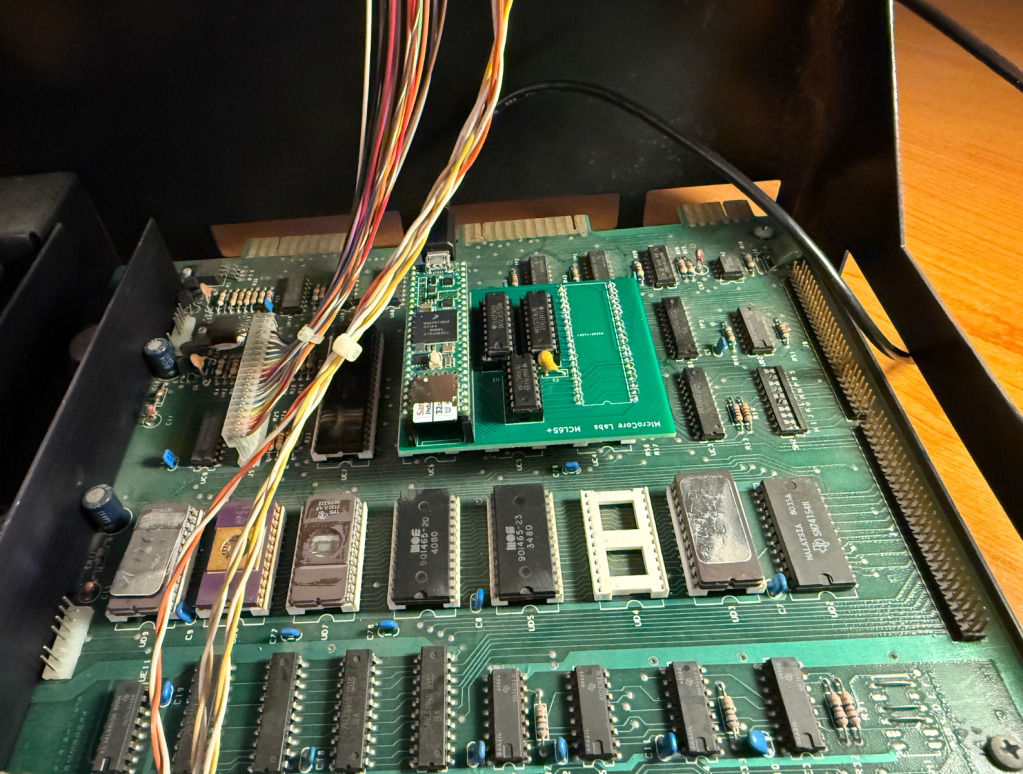
My PET 4016, which normally contains 16 KB of DRAM, was upgraded to 32 KB by a previous user. This motherboard had holes drilled in the second DRAM bank by Commodore to keep users from upgrading their 4016 machines to 32 KB in and to force them to buy a PET 4032. This user simple hand-soldered the drilled out connections and upgraded it anyway!

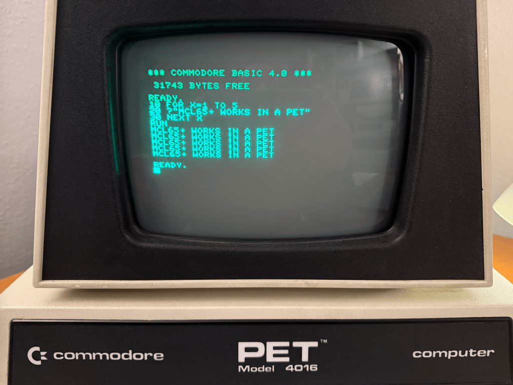
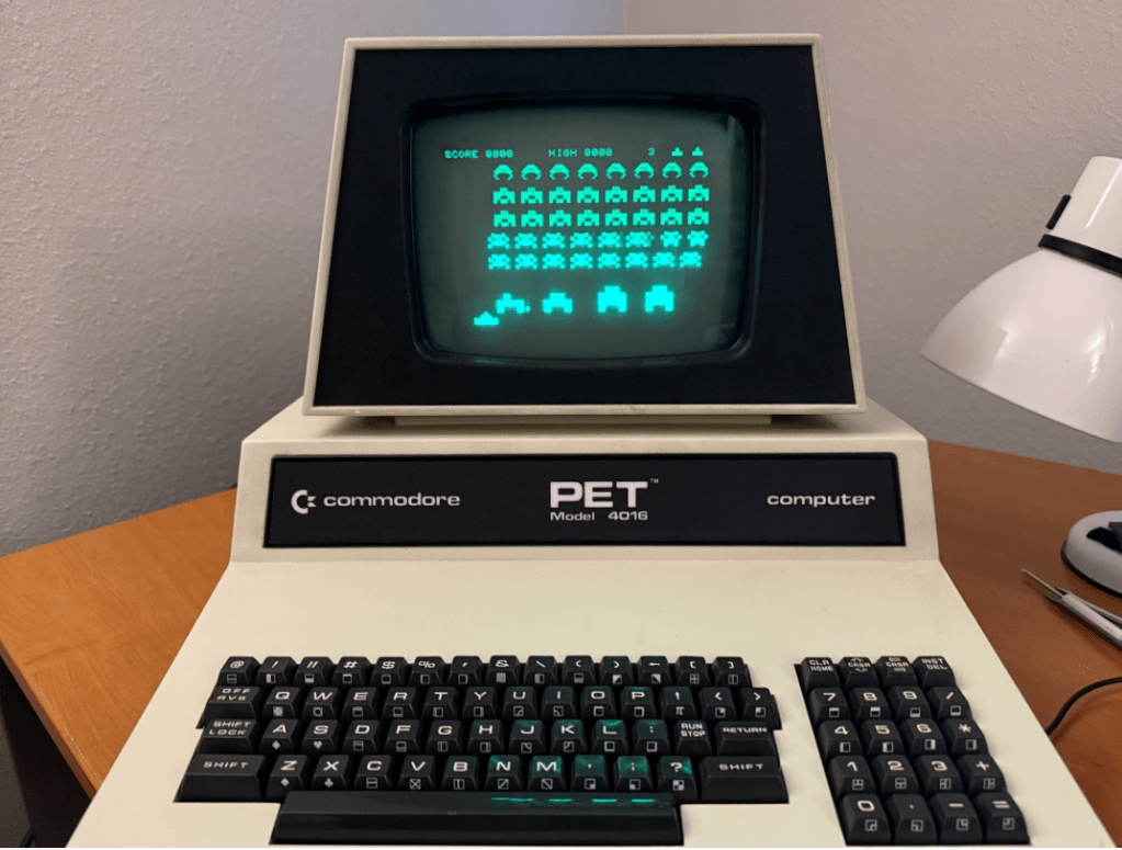
As soon as I installed the MCL65+ it was able to booting the PET and I was able to run a small BASIC program. It had no trouble replacing the 6502 in the computer.

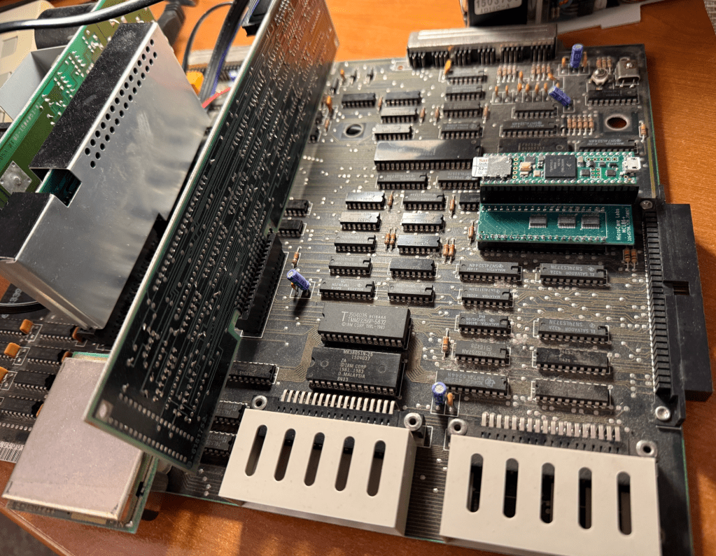
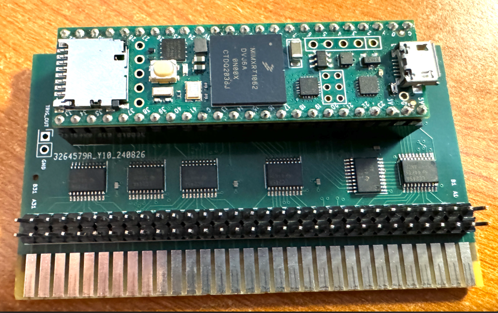
This is the MCL65+ installed in the computer’s CPU socket – replacing the 6502.

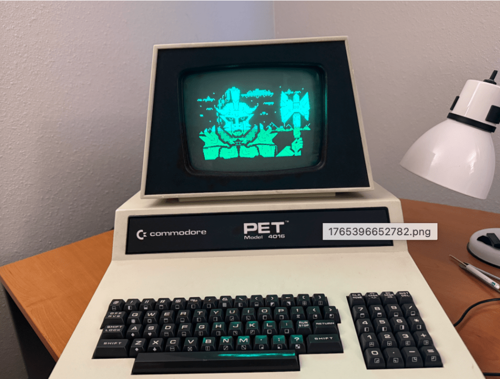
The next step was to test a theory that I had – I wondered if a .PRG program file could be loaded and run directly from the PET’s memory without needing a disk drive. This turned out to be the case!

The first two bytes of a .PRG binary file contains the memory address to locate the program and the rest of the file is simple the stream of binary data for the program. I simple converted the .PRG files to a string of hex data, placed it in an array in the MCL65+ code, and loaded it when the user presses a key.

Once the program was loaded I just needed to type RUN in BASIC and the program started up!

Being able to replace the 6502 and run programs directly from the internal memory was interesting, but I though it would be even more amusing to try some acceleration modes of the MCL65+ to see how fast we can run a Commodore PET.

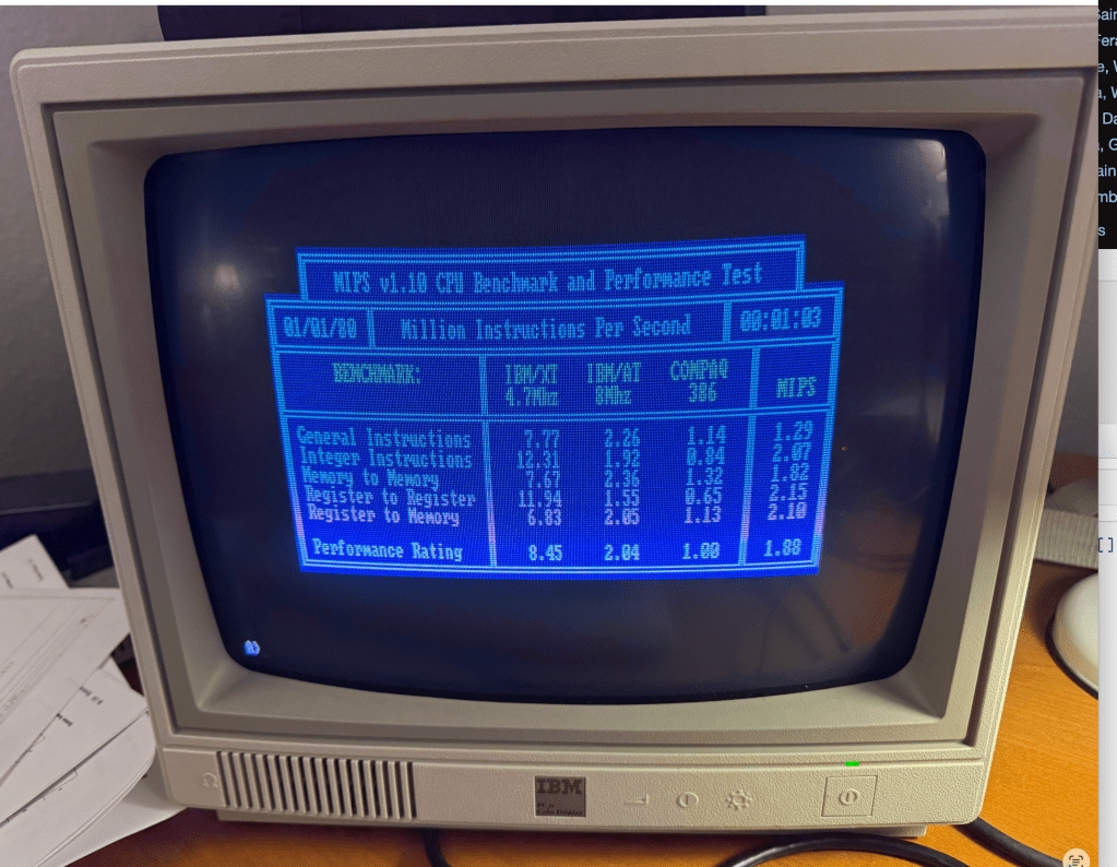
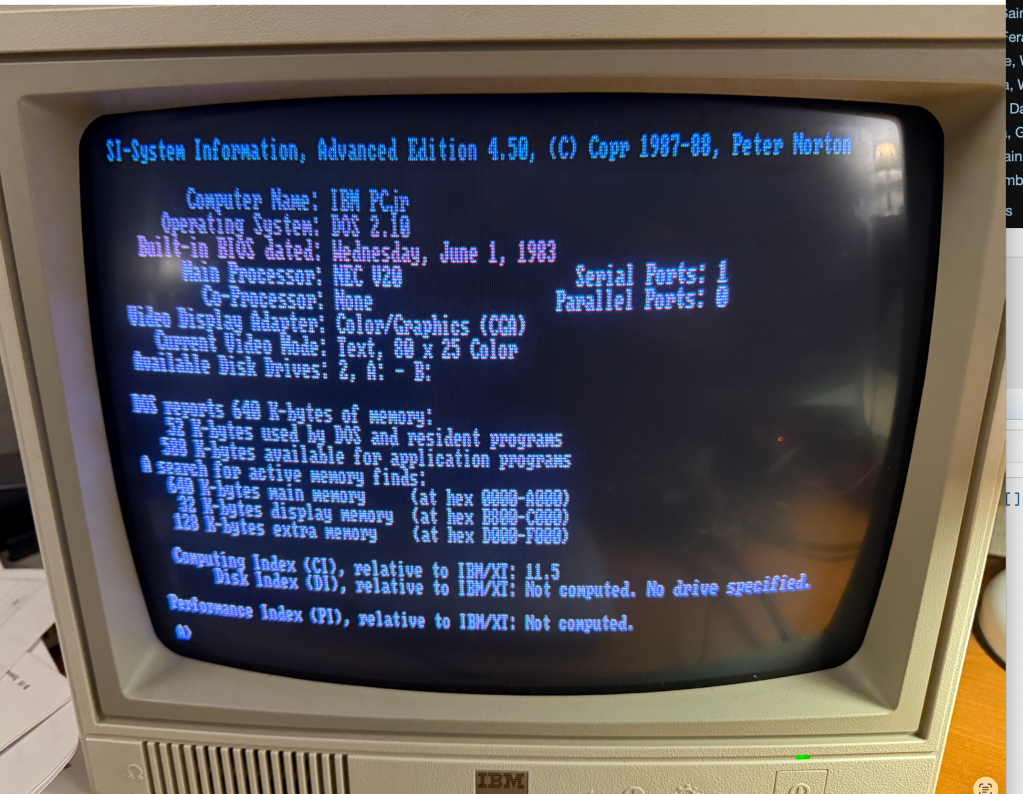
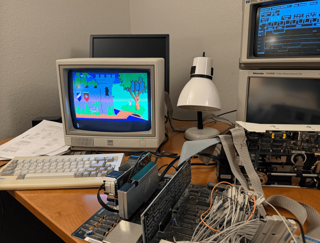
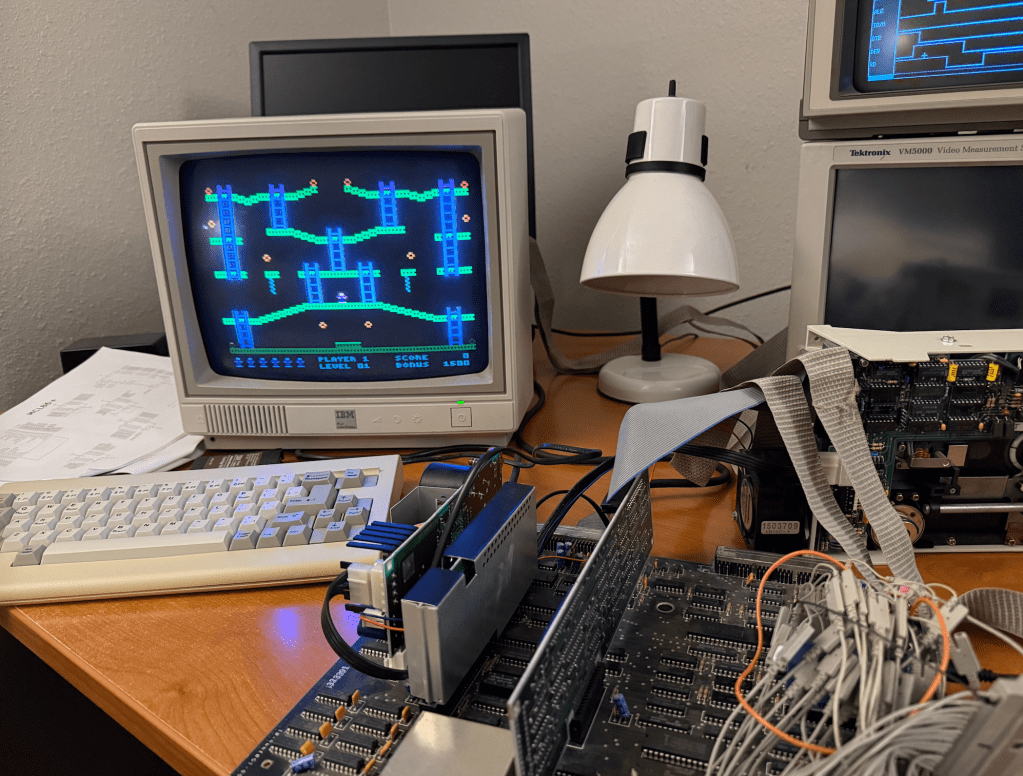
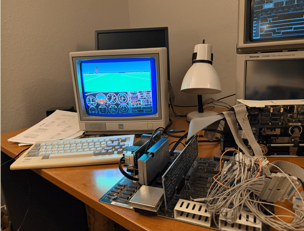
Here is a video demonstration of me running a few programs and diagnostics using a few acceleration modes:


The MCL65+ uses a Teensy 4.1 which contains 1 MB of memory so it can easily emulate all of the PET’s ROM and RAM. With just a few line of code it can emulate different PET ROM images and diagnostic ROMs, support different sizes of system memory, and can mirror these memories in a cycle accurate or accelerated manners.

The video shows the computer running three acceleration modes. Mode-1, Mode-2, and Mode-3.

Mode-1 is cycle accurate where the MCL65+ runs just like a stock 6502 and is cycle accurate for both reads and writes. Mode-2 is cycle accurate on writes but accelerated on reads. Mode-3 is accelerated on both reads and writes. The accelerated modes store all of the computer’s RAM and ROM inside of the MCL65+ internal memory and run it at the maximum speed of the Teensy which is 900 MHz and clock accuracy is not observed.

I believe this machine is now the World’s Fastest Commodore PET!

World’s Fastest Commodore PET using the MCL65+ 6502 drop-in emulator

8088 CPU Emulator for the IBM PCjr – MCL86jr+

I got the MCL86+ running on the IBM PCjr by adding 8088 minimum mode support plus a few modifications to the PCB.

Project on GitHub: https://github.com/MicroCoreLabs/Projects/tree/master/MCL86%2B

Cycle accurate mode appears to work fine so I next added some acceleration by removing clock counting and mirroring all 640 KB inside of the Teensy. According to MIPS.COM, this IBM PCjr is as fast as a 80386.

The only issue I am running into is the inability to write to the floppy drive. Reads work fine but writes are inconsistent. I’m fairly sure I know why…

Early in the development of the MCL86jr+ I found that the PCjr BIOS is very (overly) reliant on 8088 instruction and bus timing. 

Here is what I found:

In the BIOS POST CRT Attachment Test the MCL86jr+ would fail with ERROR 0908 and halting. Once I compared the sequence on a logic analyzer with a genuine 8088 I could see that the MCL86+ was performing opcode prefetches at the end of opcodes while the real 8088 interspersed them throughout the opcode execution. This resulted in the MCL86jr+ opcode execution being “tighter” and ready to accept interrupts earlier than the genuine 8088 could. 

Shortly after the OUT opcode at address 0xF0452 which enables the vertical retrace interrupt was executed, the MCL86jr+ would accept and process the interrupt which disabled the source even before the main loop at address 0xF0459 had started. This code is not well written and is dependent on specific bus timing and recognition of the interrupt. 

Also, I am certain that interrupts were already enabled before address 0x0F458, so the STI opcode should not have been necessary. I wonder if they added it as an attempt to guarantee that interrupts would not be accepted until at least the end of the TEST opcode. (They knew that interrupts are not accepted at the end on the STI opcode). Seems like a sloppy solution.

My guess is that there is another timing-dependent piece of code somewhere in the floppy write routine which is not tolerant of big differences in the MCL86jr+’s approach to opcode and bus timing.

8088 CPU Emulator for the IBM PCjr – MCL86jr+

XTMax – 8-bit Software-Defined ISA card using Teensy 4.1

XTMax is a software-defined 8-bit ISA card which uses a Teesny 4.1 microcontroller board that provides the functionality of THREE vintage ISA cards. It can expand “conventional” motherboard RAM up to 640 KB, adds up to 16 MB of Expanded RAM, supports 320 KB of UMB RAM, and provides bootable hard-drive access using a MicroSD card. A small PCB is used to allow nearly all of the ISA bus signals to attach to the Teensy 4.1.

A similar project to this is the PicoMem which is also a software-defined ISA expansion card, however the Teensy 4.1 used on the XTMax is nearly 3X faster than the Raspberry Pi Pico so does not share some of its limitations.

The first feature of XTMax is that it can expand the motherboard’s conventional (motherboard) ram up to 640 KB without limitation and with zero wait states. XTMax also has no limitation on the ability to support DMA to and from the computer’s floppy or spinning hard disks as PicoMem does.

XTMax can currently support 16 MB of Expanded RAM and 320 KB of UMB using a updated drivers.

XTmax also allows a MicroSD card to be accessed as a hard drive which is similar to the functionality of an XT-IDE card. By default it will be the boot device if there is no hard drive present.

All design files are open souce and posted to GitHub:

https://github.com/MicroCoreLabs/Projects/tree/master/XTMax

Here is the PCB developed using KiCAD:

And here is the actual board with a Teensy 4.1 attached:

Here is XTMax installed in a very early IBM 5150 rev-A which has 64 KB installed on the motherboard.

It shows that 4 MB of Expanded RAM was added and that the MicroSD card is accessible as the C: drive. The older IBM PC’s did not display the total amount of conventional memory, but in this application below the memory is expanded to the maximum of 640 KB.

It is worth noting that the first BIOS version of the IBM PC did not support extension ROMs and therefore do not support hard disks, so XTMax is currently the only way to have a hard disk equivalent on these machines!

Here is the total memory on this early PC as reported by Norton Utilities:

Here is a screen capture of the XTMax providing 16 MB of Expanded RAM and loads the UMB driver plus configures a 15 MB RAMDISK!

I posted a video on YouTube of the XTMax in action:

XTMax – 8-bit Software-Defined ISA card using Teensy 4.1