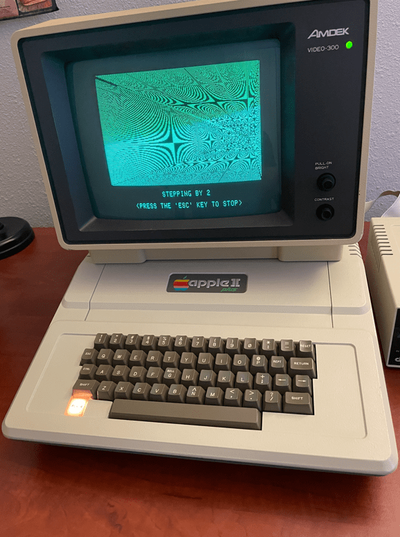
I first run the MCL65+ core in mode 1 which is 6502 cycle-accurate where each screen of the demo takes around 30 seconds. I then change to mode 2 acceleration which mirrors the computer’s memory with reads running accelerated and writes running cycle-exact while updating the computer’s memory. Basically, reads are accelerated and writes are cycle-accurate and pass through to the computer’s memory. I then change to mode 3 which uses mirrored memory and both reads and writes are accelerated!
I am changing acceleration modes using a series of keystrokes on the Apple II+ . I press left_arrow, right_arrow, left_arrow, then the number for the desired acceleration.
The MCL65-Fast is a drop-in replacement for the 6502 CPU however it does not emulate the processor. Instead it allows you to run C code compiled on the Arduino GUI to run directly on the Teensy 4.1’s 32-bit ARM A9 which is an 800Mhz+ superscalar CPU. This provides the ability to write C code to run on this fast CPU in the place of the vintage computer’s 6502!
I uploaded a YouTube demonstration which uses it in an Apple II+ seen here:
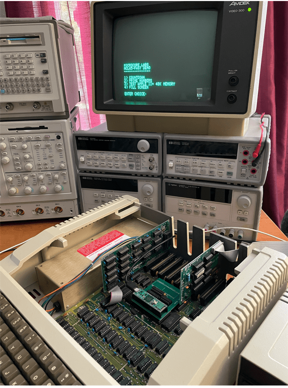
The MCL65-Fast has control over the 6502 bus so it has access to all of the motherboard’s peripherals and slots which include the keyboard, video, sound, and anything plugged into an expansion slot. To access the Apple II video and keyboard, I have included a printf, and scanf, and other functions to display characters to the Apple II’s video as well as access its keyboard. With these functions you can write programs using regular C code and use printf and scanf to accept input and display the results!
The YouTube demo video shows how fast the MCL65-Fast runs inside of an Apple II+. I first show the board running the MCL65+ 6502 in cycle-accurate emulation mode and then download the MCL65-Fast code which demonstrates a few small functions which show the incredible speed!
The MCL65-Fast would be fun for people who would like to develop programs for the Apple II or other 6502 computers while using the modern and easy to use Arduino tools. It is also fun to see these vintage machines running at ridiculously fast speeds!
The following are some notes on how to install and configure a system to load code into the MCL65+.
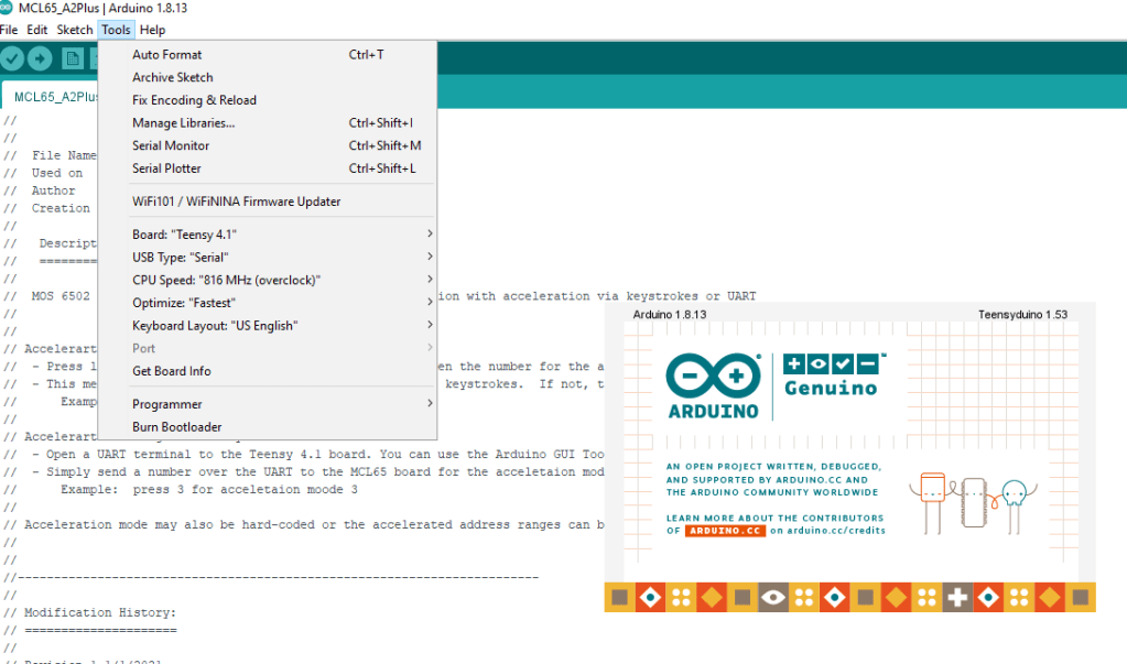
ONE: The first step is to load a special version of the Arduino GUI and the Teensyduino tool on top of it. Personally, I am running Arduino GUI version 1.8.13 on my computer.
TWO: The MCL65+ is implemented using a Teensy 4.1, so the Arduino tools need to be configured for this board. Select the Teensy 4.12 board, the CPU Speed set to 816Mhz, and the Optimize to “Fastest”.
THREE: I have uploaded a few versions of the MCL65+ to GitHub which include a generic 6502 as well as a version for the Apple II+. Each of them have the ability to run in accelerated modes.
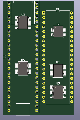
FOUR: Remember to cut the solder-pad jumper indicated below so that the MCL65+ and Teensy 4.1 board can be powered using the computer’s power supply alone. If this jumper is not cut, then there will be a connection between the USB and computer power supplies!
FIVE: The MCL65+ supports four acceleration modes. Modes 0,1,2 and 3.
0x0 – All 6502 bus cycles executed using external memory accesses to the motherboard – No acceleration 0x1 – Reads use cycle accurate internal memory and writes pass through to motherboard – No acceleration 0x2 – Reads accelerated using internal memory and writes pass through to motherboard – Accelerated mode 0x3 – All reads and writes use non-cycle accurate accelerated internal memory – Greatest acceleration mode
Please note that the computer’s video address range cannot be accelerated to mode 0x3 because in this mode writes do not go to physical memory.
The acceleration mode can be changed in three ways: 1) statically in the C code. 2) Using the JTAG UART. 3) Using a series of computer keyboard keystrokes which is currently only supported on the Apple II.
Method 1 – Change acceleration mode statically in the C code. The code snippet for the Apple II+ version is below. You can set the mode to a specific number, or you can set it to ‘mode’ which allows it to be changed with either the UART or the keystrokes.
Method 2 – Change acceleration mode using the JTAG UART. Using a serial terminal such as the Arduino’s Serial Monitor or TeraTerm, simply send type the digit 0,1,2 or 3 to change the acceleration mode.
Method 3 -Using a series of computer keyboard keystrokes which is currently only supported on the Apple II. Press a keystroke sequence of the left-arrow(L), right-arrow(R), left-arrow(L), then the number to change the acceleration mode. Note that this method only works if the Apple II program or game is scanning for keystrokes. If not, then the UART method of acceleration must be used. For example: press LRL3 to enter acceleration mode 3
SIX: Partitioning address ranges. As seen above, you can allocate different acceleration modes to different address ranges. In the example above you can see the range 0x0400 to 0x0C00 was set to acceleration mode 0x1 which means all CPU writes will go out to the physical video RAM on the motherboard. Other ranges specific to the Apple II were partitioned and assigned their own acceleration mode. You can partition these ranges to any target computer. The default is acceleration mode 0x0 in which all 6502 accesses go out to the computer’s physical motherboard which is identical to the original 6502.
Notes:
When accelerating the Apple II, the disk drive will not be able to work. This is because the firmware driver uses software loops which are dependent on the speed of the CPU. When accelerated, these loops run too fast for the disk drive to respond!
Be careful not to accelerate accesses to video memory ranges or else the display will no longer work.
Some computers use software to draw to the display which may be dependent on the speed of the CPU. No acceleration could be achievable in this case.
To achieve the maximum acceleration, all RAM and BIOS ROMs should be copied into the internal memory and use acceleration mode 0x3. Only the computer’s video RAM should use mode 0x2.
Well at least *one* of the the world’s fastest Commodore 64’s 🙂
There are also the SuperCPU and Chameleon FPGA platforms which are either extremely expensive or unobtainable. The MCL64 board coupled with the Teensy 4.1 cost less than $50!
When I locate most of the C64’s memory ranges inside of the micro controller and disable cycle accurate mode (1Mhz native mode) the 6510 is emulated at over 600Mhz on a dual-issue superscalar processor, so it’s no surprise that we can achieve such a speed improvement!
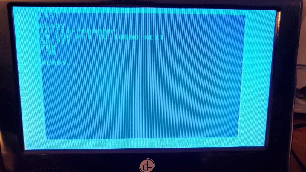
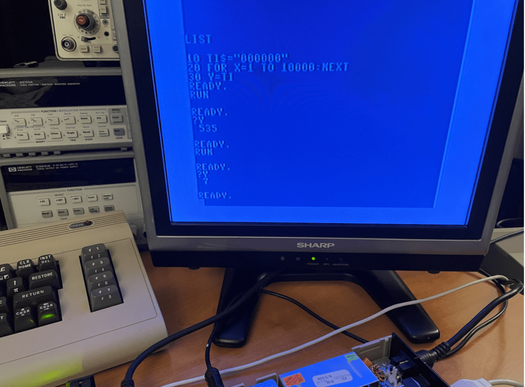
I am basing the speed increase on a small BASIC test which counts the “jiffies” during a loop of code. This is the method used by the YouTube host “8-Bit Show and Tell” during his demonstration of the Super CPU Commodore 64 accelerator board:
In cycle-accurate mode my MCL64 measures the same results as the host, but when comparing the Super CPU accelerated to 20Mhz and the MCL64 in its accelerated mode, the MCL64 is roughly 2X faster than the Super CPU (in raw accelerated mode). The Super CPU has an additional “optimized” BASIC acceleration mode which further speeds up the hardware; however if the MCL64 implemented this optimization it would most likely again be much faster than the Super CPU.
This is the YouTube demonstration of the Super CPU running in its 20Mhz acceleration mode:
This is the MCL64 running in its accelerated mode which is more than 2X faster than the Super CPU:
Small update on 12/12/2021: I created a stripped-down version of the MCL64 code which eliminates all of the 6502’s extraneous reads and writes and tried the BASIC test code once again. This time the test took around 7 jiffies! (The first pass which yielded 525 was using this optimized code without acceleration enabled)
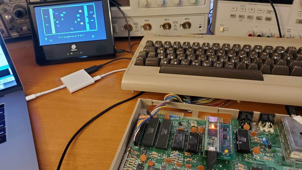
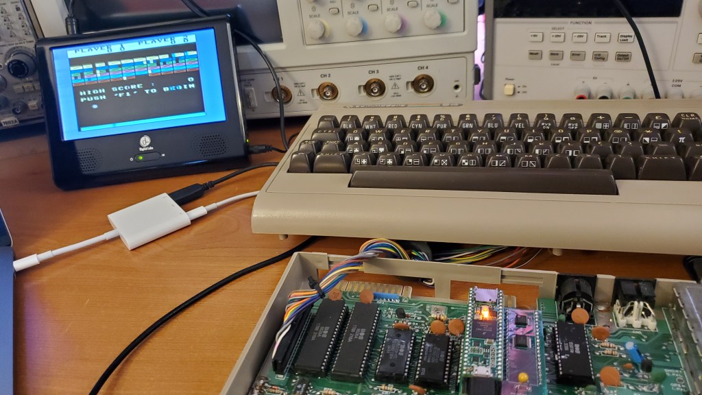
Here are a few C64 cartridge images which I loaded into the MCL64:
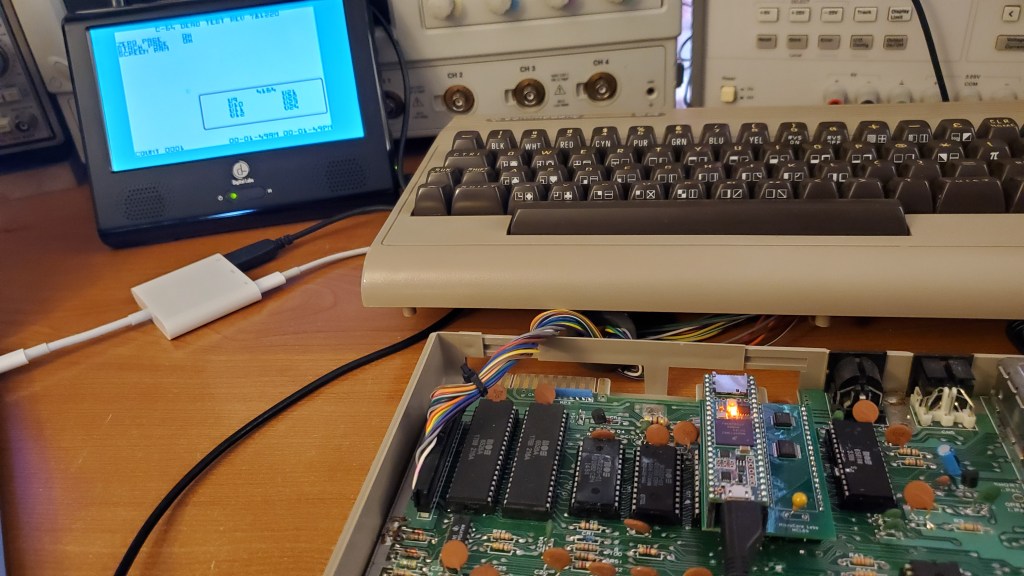
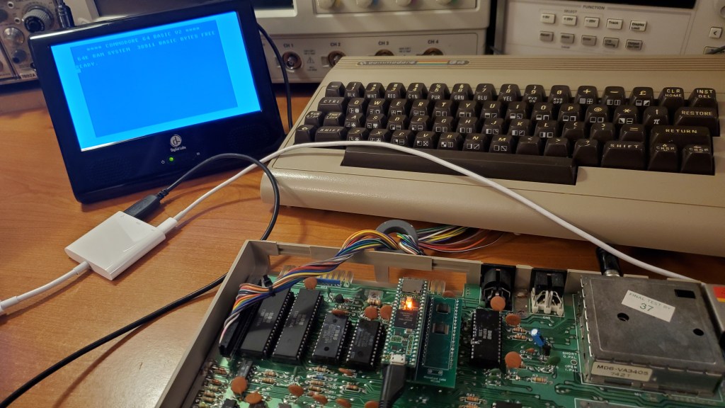
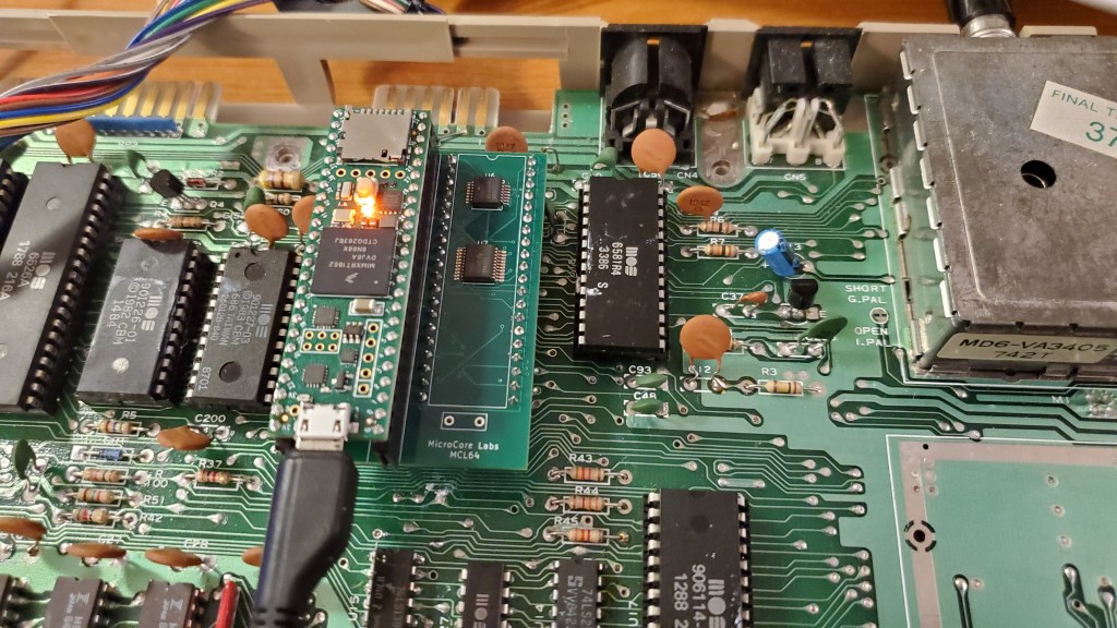
I received my MC64 PCB in the mail today which I plugged it into my Commodore 64 and was happy to get some decent results!
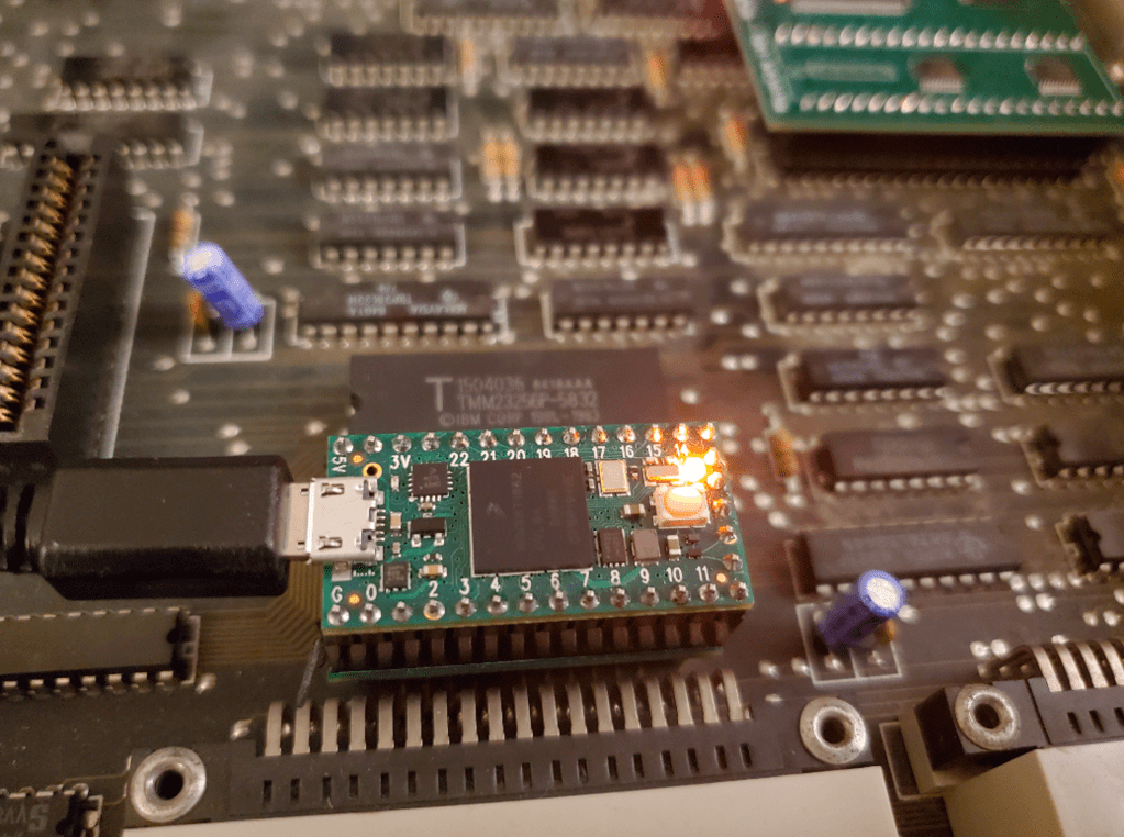
The MCL64 is a port of my MCL65+ project to the MOS 6510 pinout so it can be used as a drop-in replacement for the Commodore 64’s CPU. It uses my 6502 emulator which runs on the Teensy 4.1 which is an Arduino-like board which runs at 600Mhz+ and has 1MB of memory. The 6510 emulation can either be cycle accurate or it can run significantly faster than the original processor!
I am able to boot to BASIC and run a print “Hello World” program, so one of the next steps will be to try running some of the C64 cartridge images directly from the processor’s on-board RAM. I will probably need to add some code to support the C64’s bank switching internally to do this.
I thought an EPROM emulator would be a cool application of a Teensy 4.0 and a small PCB.
The EPROM is emulated using a Teensy 4.0 which has more than enough speed to sample the 16 address lines, retrieve the data from a 64KB array, and then drive the data lines.
It supports EPROMs sizes up to the 64KB 27C512. Uploading a new ROM image takes seconds and is as simple as updating the data array then reprogramming the it using the Arduino’s IDE.
The small PCB contains three SMT buffers to convert voltages since the Teensy is not 5V tolerant. This board plugs into the EPROM socket and the Teensy plugs into this board.
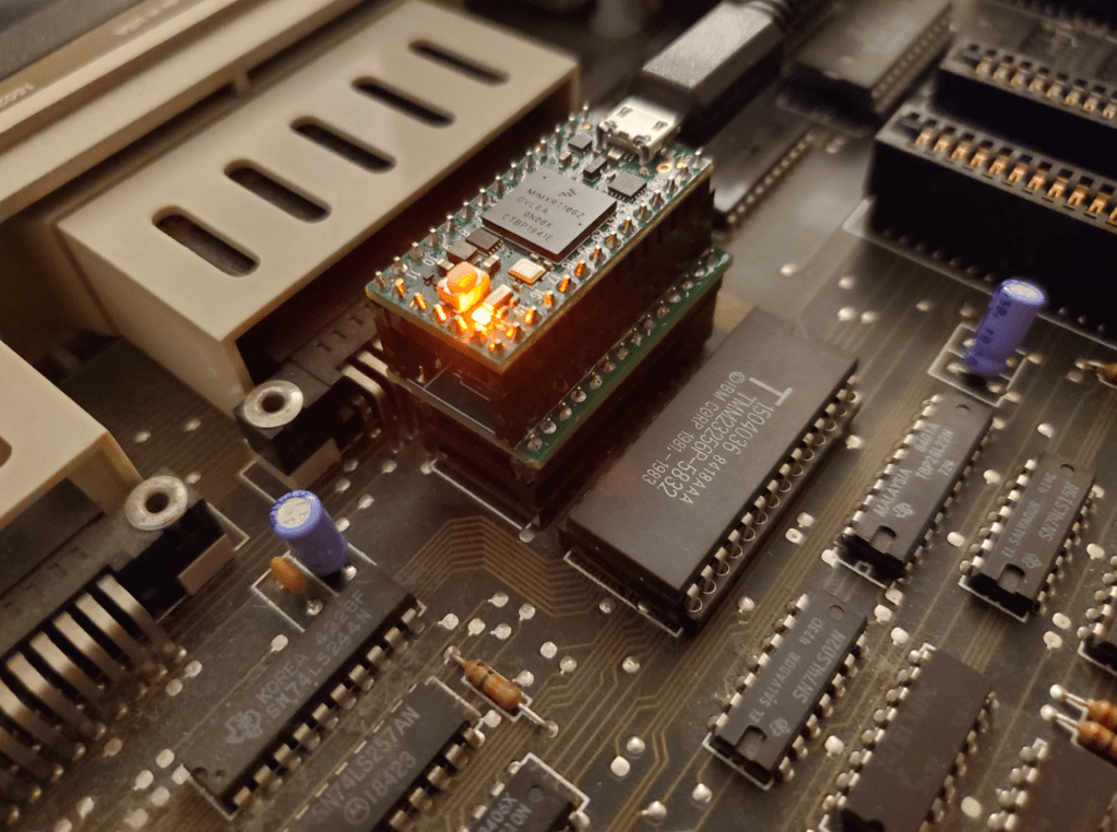
The setup you see below is somewhat tall because, rather than soldering the Teensy directly to the board, I used sockets between the Teensy and the PCBA which added a lot of height. Without these sockets it would be much shorter.
I am working on a 6510 version of the MCL65+ which can be used in a Commodore 64. A few more buffers are needed to support AEC and the Peripheral pins, but it is basically a 6510 layout of the system which works in the Apple II+ and the VIC-20.
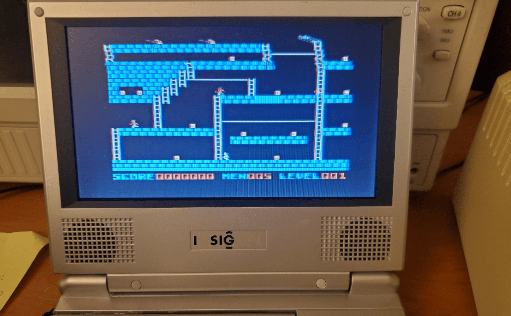
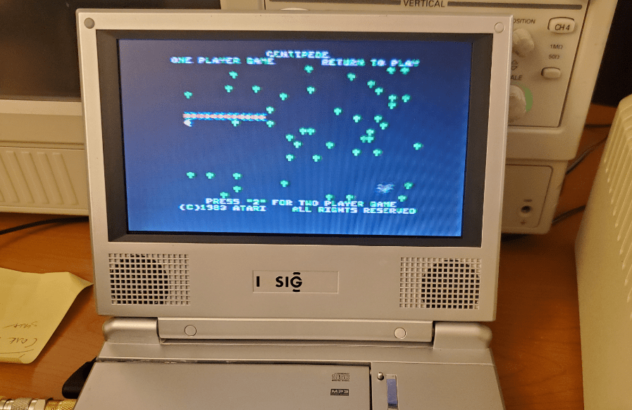
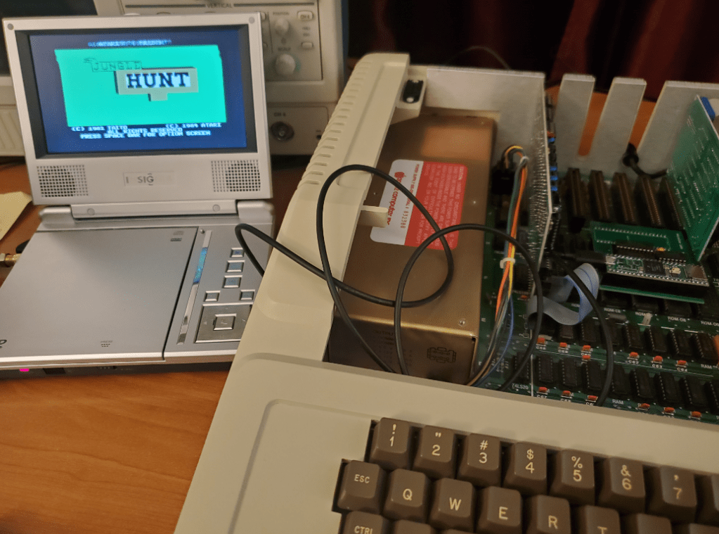
I thought I would finish up this project with a few pictures of some games using the MCL65+ in cycle-accurate mode as a drop-in replacement for the Apple II+’s 6502.
Another flashy title, but again probably true! The MCL65+, when running in accelerated mode is, I estimate, more than ten times faster than a stock 1Mhz Apple II+! This was accomplished by emulating all of the computer’s ROM and RAM in the 600Mhz microcontroller’s memory. Just the I/O and video memory ranges were left as regular 6502 bus access to the motherboard which run at 1Mhz.
The MCL65+ is a 6502 accelerator card which uses a 600Mhz Arduino Teensy4.1 microcontroller to emulate a 6502 microprocessor as well as its bus interface signals. It was designed to be a drop-in replacement for the original 6502 processor found in computers like the VIC-20, the early Apple computers, and others.
I took some videos of two BASIC programs I made to measure the system’s performance before and after the acceleration. One is the classic x=x+1, print x, goto 10 program and the other prints an array of characters. Both very simple however the accelerated speed increase is dramatic.. the text just flies by!
I was surprised that the video and keyboard worked so well under acceleration! The next thing I need to try is booting the computer from either the 5.25″ diskette drive, or a compact flash drive emulator…
Here are some videos of it running with acceleration enabled and disabled. Please note that these programs print a lot to the screen which is accessed via the 1Mhz 6502 bus to the video memory and slows the test down. If less is printed to the screen the acceleration is even faster…