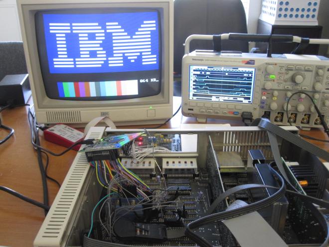
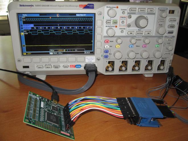
I added 128KB of memory inside of the FPGA and disabled the MCL86 cycle compatibility with the original 4.77Mhz 8088 processor and got some interesting results:
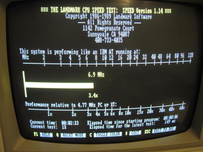
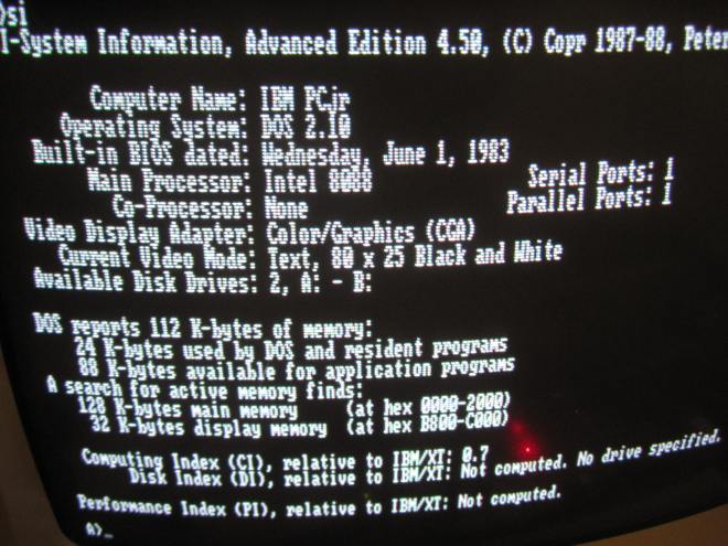
If these speed test results are to be believed, then this IBM PCjr is many times faster than the original IBM PC XT and, for some tests, even faster than the 6Mhz IBM PC AT.
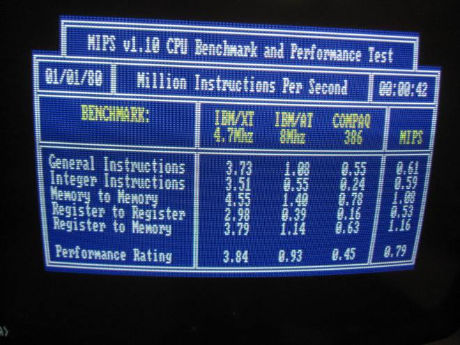
I am using DOS 2.1 and PCJRMEM.COM /C to allow these test programs to run from the upper/faster 128KB of memory.
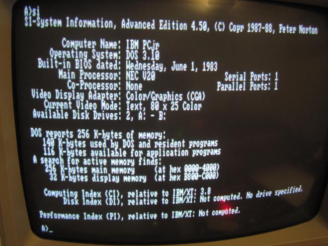
It is interesting that Norton Utilities SI.EXE now thinks the processor is a NEC V20. I think this may have something to do with the prefetch queue and the speed at which it fills when running programs from the upper/fast memory.
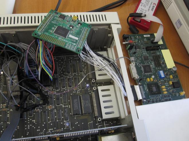
The lower 128KB physical DRAM is accessed in the normal fashion with four to six 4.77Mhz clock cycles. The upper 128KB is located inside of the FPGA and is accessed in a number of 100Mhz clock cycles, so it is many times faster than the 4.77Mhz local bus.
The MCL86 clock cycle compatibility mode is turned off once the PCjr exits it’s POST. This means that once the microsequencer finishes processing an instruction it immediately fetches the next one. With cycle compatibility turned on, the microsequencer will pause for the same number of 4.77Mhz clock cycles that the original processor takes for that instruction.
Is this the world’s fastest IBM PCjr? 🙂
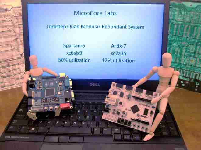
Please visit us at: www.MicroCoreLabs.com for more information.