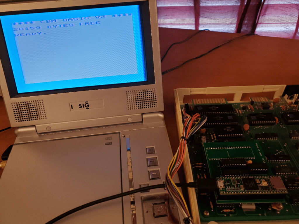
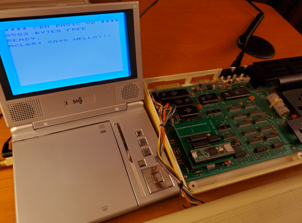
I thought I would give this post a catchy title, and I believe it is probably true! The MCL65+ runs an emulated 6502 on a 600Mhz microcontroller, so when it is not running cycle-accurate it is quite a bit faster than the original 1Mhz 6502 in a VIC-20.
Here are some of the details:
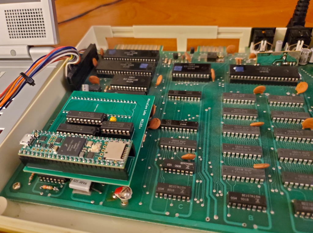
The MCL65+ can emulate the complete 64KB of the 6502’s address range at 600Mhz, so I was able to add certain components to see what worked and what didn’t. It turns out that the VIC-20 BASIC was not tolerant of much acceleration… When I ran an accelerated ZeroPage and Stack range the performance boost was only about 15%. This is because when I tried to accelerate the BIOS and video regions, the VIC-20 video would no longer work. I guess there are timing dependancies with the BIOS that must not be exceeded.
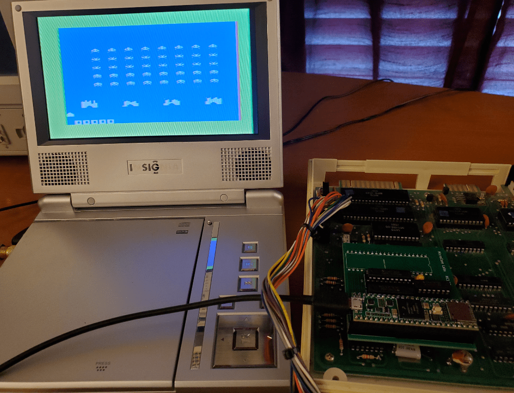
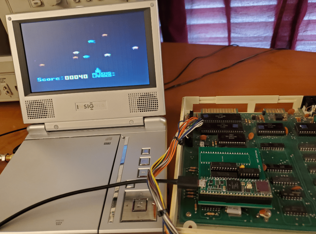
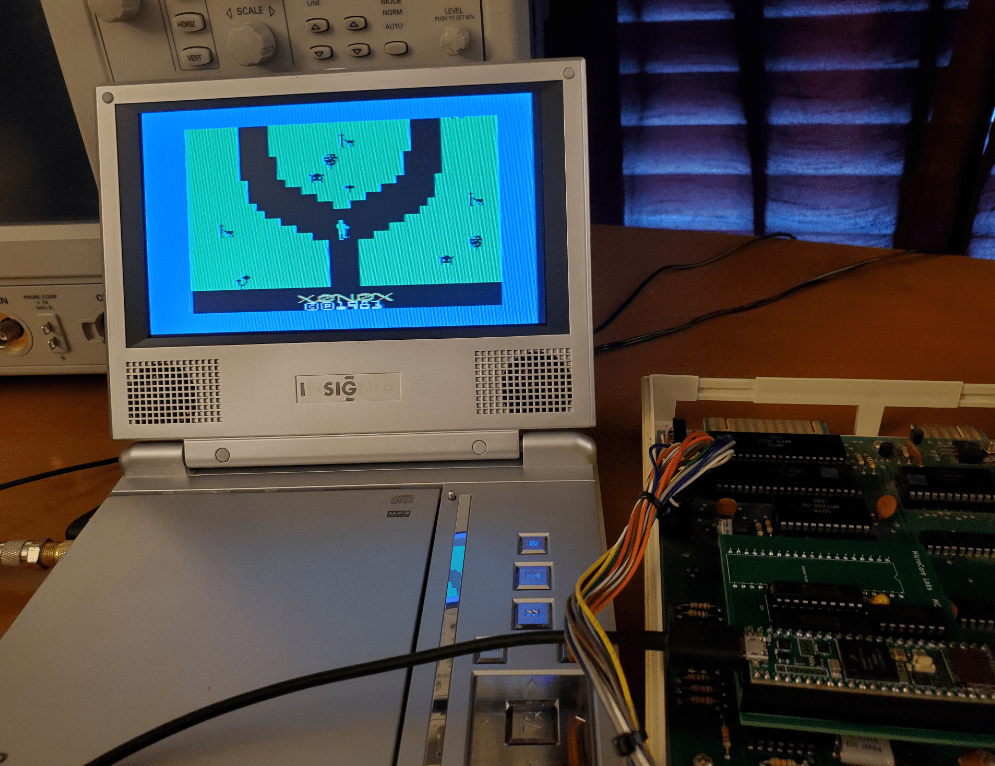
I had better luck with some of the cartridge games. Some of them actually ran better when they were accelerated because, at the normal clock speed, they were slow and less responsive! When accelerating the game and VIC-20 memory ranges they ran much faster which was more enjoyable. Donkey Kong, Pac-Man, and Jungle Hunt all ran well at the accelerated speed. Defender was a little too fast to control!
I will post some videos of the accelerated games so you can behold the World’s Fastest VIC-20! 🙂