There were a number of challenges which needed to be overcome to be able to emulate the Intel 8088 correctly, be cycle accurate, and allow the MCL86+ to actually replace the Intel CPU in an IBM PC.
The initial concept was to see if it was possible to use the speed of an 800Mhz microcontroller to both emulate the 8086 instruction set and also manage the 8088’s local bus interface which is running at 4.77Mhz. I had recently finished the MCL65+ which is similar 6502 emulator, however this CPU only runs at 1Mhz – so 4.77Mhz was going to be more challenging, if possible at all…
I wrote some code which performed basic reads and writes on the local bus and was not surprised to find that it did not make timing. I tried direct accesses to the Teensy’s GPIOx registers to allow for a faster and more parallel accesses to the IO pins which still wasn’t fast enough due to the bit shifting and isolating to steer the 8088 address and data signals to the correct Teensy GPIOs. I found that using a few arrays to perform this mapping reduced this translation time significantly. For additional margin I am also running the Teensy 4.1 overclocked at 800Mhz which, according to the GUI, does not need cooling and I have found that it runs reliably at this speed. I also noticed that occasionally 8088 clocks were being lost, so I disabled Teensy interrupts while an 8088 bus cycle is in progress. After this code was running reliably I could then begin development of the MCL86+ PCB.
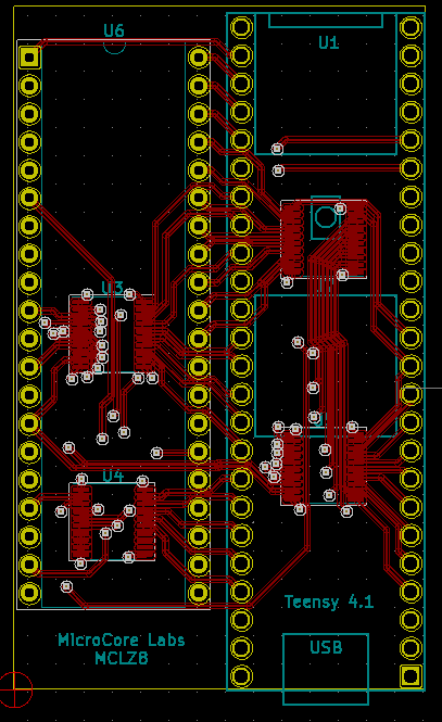
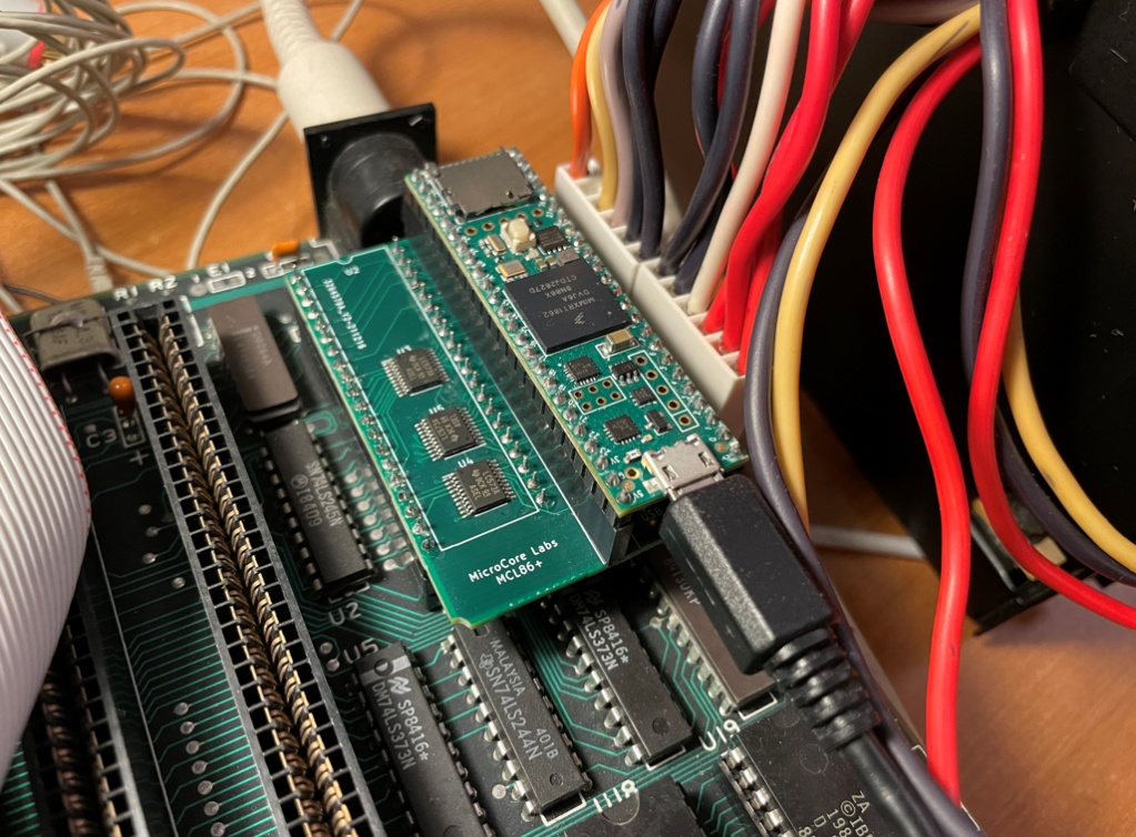
I used KiCad to generate the schematics and PCB layout. I tried to select Teensy IOs which closely routed to the appropriate 8088 pin and also to maximize the Teensy’s GPIOx register utilization. Because the target of this project was to run on the IBM PC I only needed to support the 8088’s Maximum mode which meant I would only need three 8-bit buffers on the MCL86+ to perform voltage translation. The Teensy 4.1 had enough pins to allow me to separate the databus inputs and output pins which would yield faster bus timing since I would not need to program the Teensy IO/s to change direction between input and outputs.
While the PCB was being built I had time to write the code for the 8086 emulator. A few years ago I wrote an x86 emulator for my MCL86 project which is a microsequencer-based FPGA core which also runs cycle accurate and accelerated modes, so I was already familiar with the 8088’s instruction set and also the “structural” aspects of the processor such as the ordering of interrupts, the operation of the prefix opcodes, and the prefetch queue.
The 8088 emulator code, like the real 8088, is divided into two sections: The Bus Interface (BIU) and the Execution Unit (EU). This allowed me to either use a BIU which accesses the real 8088 pins, or instead use a “fake” BUI which uses arrays for RAM and ROM so I cold develop and test the emulator using command-line C and printf’s. I wrote a number of opcodes tests fort the 8086 when I developed the MCL86, which saved a lot of time debugging the MCL86+.
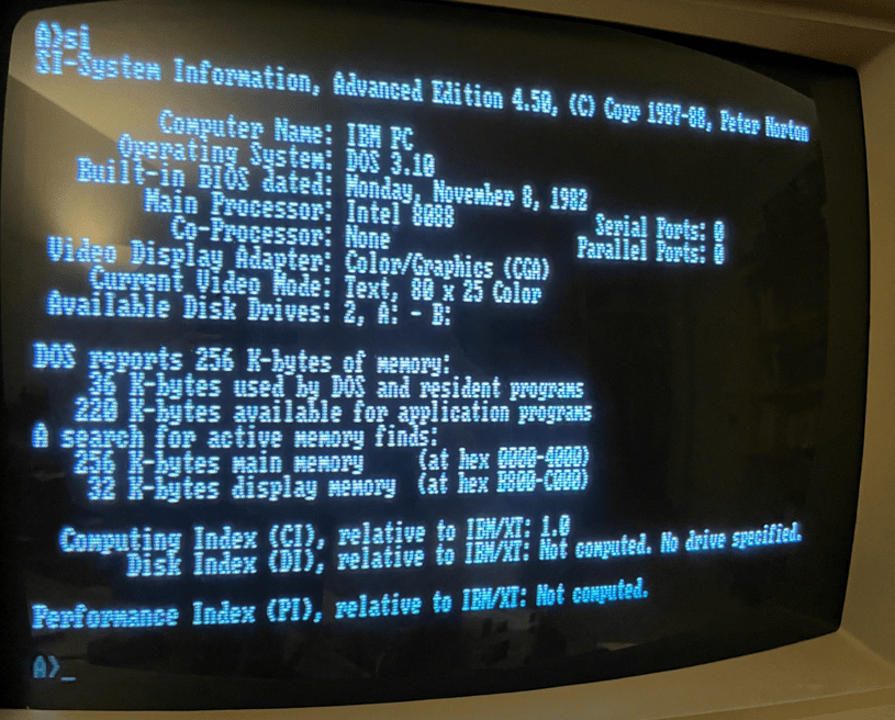
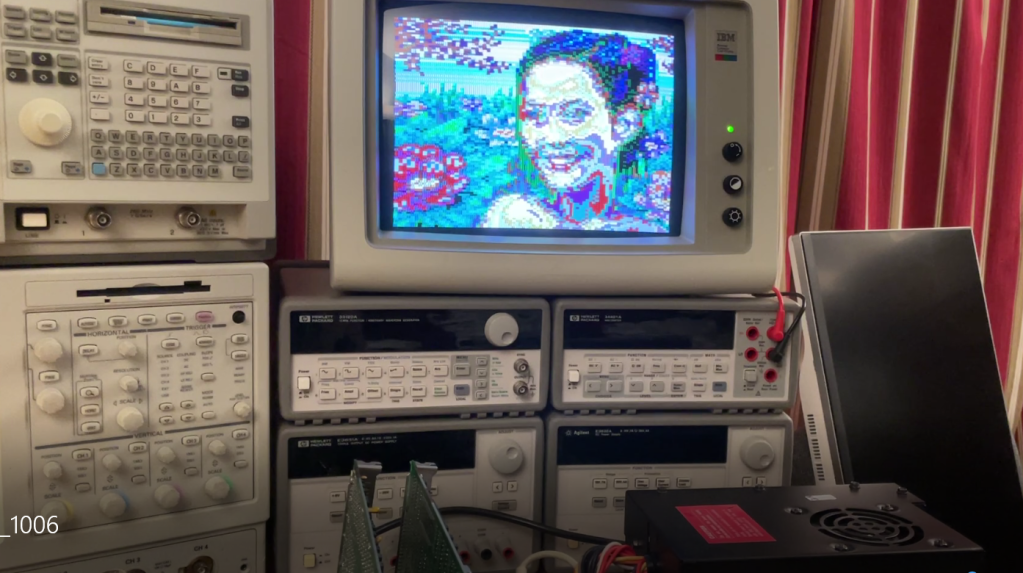
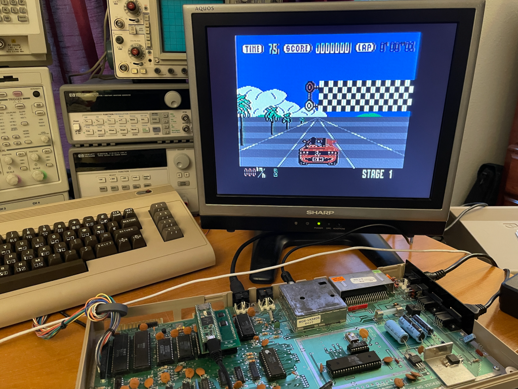
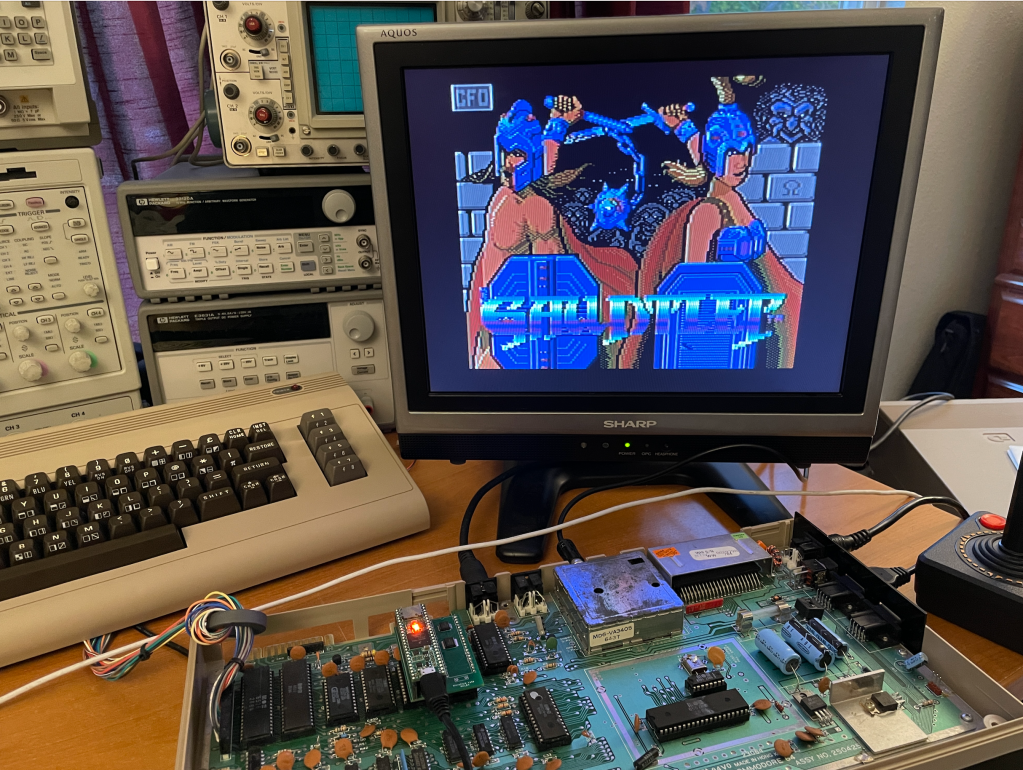
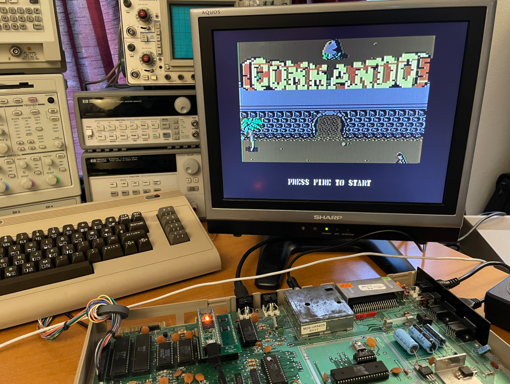
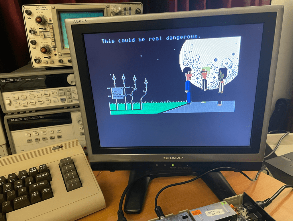
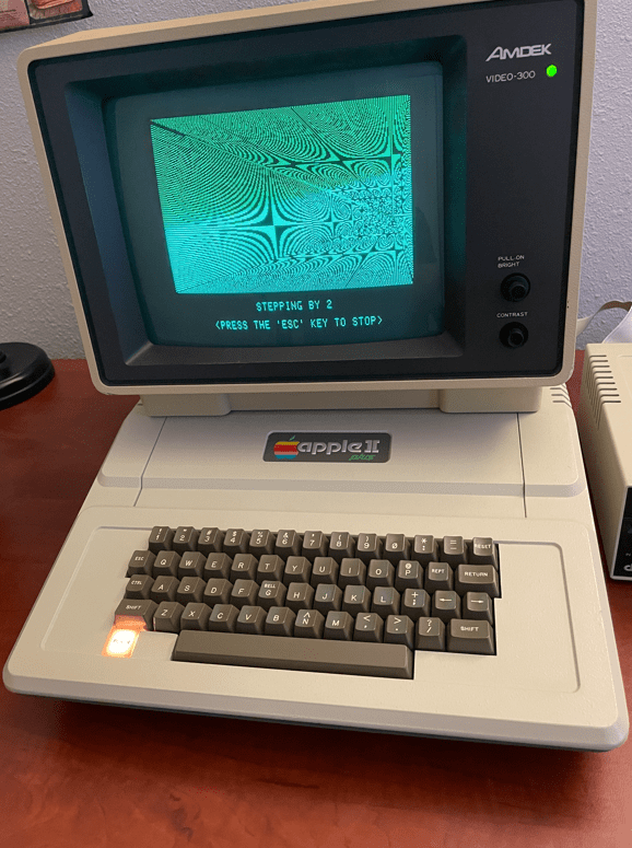
Of course the MCL86+ did not immediately work when I first plugged it into the IBM PC; however it did fetch instructions and produce some results to the CGA display when I ran the SuperSoft Diagnostic ROM. Some of the initial bugs were that I was not latching all of the 8088 address lines for the duration of the bus cycle. I also was pushing the wrong address to the stack for a CALL opcode, and the final bug was that I was not flushing the prefech queue upon one of the CALL opcodes. After that it was able to run just about any program I tried on it!
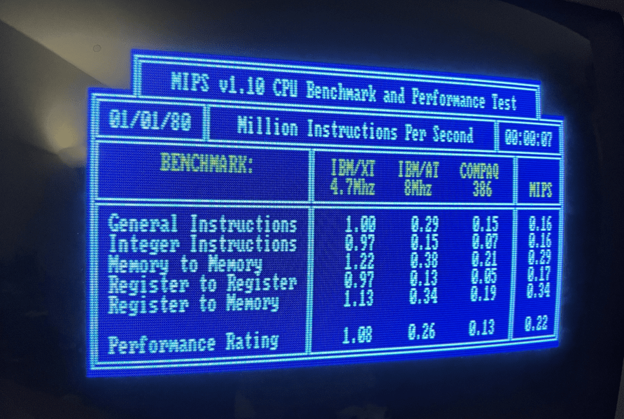
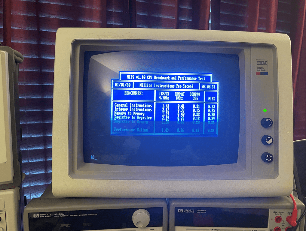
The next fun part was to try some acceleration! The first and easing thing to do was to simply disable the clock counter which allows the emulator to be cycle accurate. This yielded a nearly 50% improvement in speed as reported by a few benchmark programs. It was also not such a great degree of acceleration that things like the disk drive, keyboard, and timers seemed to still work.
I then tried integrating some of the motherboard’s RAM and ROMS and running them at the speed of the 800Mhz Teensy 4.1’s microcontroller but got very interesting, yet disappointing results…
When running the SuperSoft Diagnostic ROM the computer ran significantly faster than stock! Perhaps close to 10 times faster… But when I booted to BASIC, it will not able to accept keystrokes from the keyboard,. The speed was also too fast to boot from the disk drive; so I was not able to run any benchmarks to see what the acceleration yielded. One problem is that the IBM disk drives use DMA to copy data to/from the motherboard RAM, but if I emulated this RAM inside of the MCL86+ is it no longer coherent with that on the the motherboard, Perhaps if I had an XT-IDE which does not use DMA I could make further progress.
But, for now the design goals were met and it is time to move on to the next project.
All of the project files, the emulator source, the schematics, and the PCB fabrication files are on GitHub.