I thought it would be a fun project to use the MCLZ8 to emulate the Zilog Z80, the TRS-80 Model I ROM BIOS and DRAM, and remap the keyboard and video to the motherboard resources of the NABU Personal Computer. Now the NABU is effectively acting like a Tandy TRS-80 Model 1!
This project was built quickly thanks to already having most pieces from existing projects and only took about an afternoon to complete.
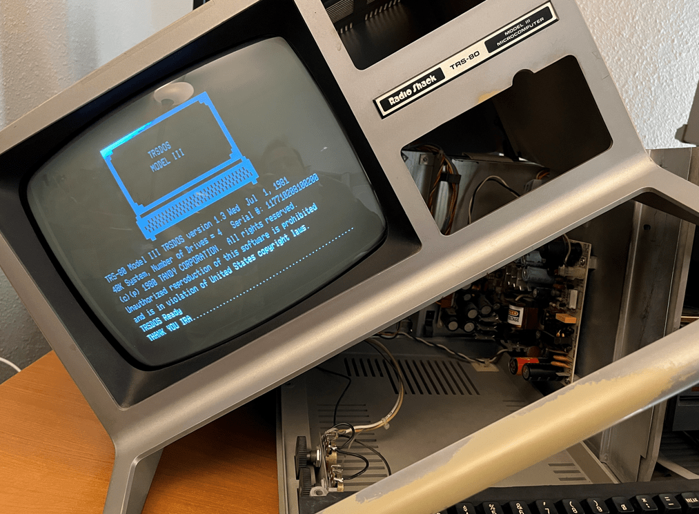
The first step was to confirm that the MCLZ8 would work in the NABU as a replacement CPU for the Z80. The MCLZ8 was previously tested to work on the TRS-80 Model III which has a slower bus speed than the NABU, but it worked the first time without an issue.
Next I added some storage arrays in the MCLZ8 to store all of the NABU’s configuration IO accesses to the video chip and keyboard. This saved me a lot of time so I would not need to learn how these chips worked from the datasheets!
I then added the TRS-80 BIOS ROM and RAM emulation into the MCLZ8 so that all accesses to these memory ranges were handled in the Teensy using an array in C.
The NABU and TRS-80 have different video sizes with the NABU being 40×24 and 64×16 for the TRS-80. Since the NABU had more vertical space I was able to start the TRS-80 video downwards 8 lines which left room to keep the NABU splash screen which I thought is a neat effect! The TRS-80 has more columns so the NABU can only display 40 of them. The characters are still there in video memory, they are just not displayed. I used an array to convert the TRS-80 row/column mapping to the NABU which is faster than performing the math…
The NABU keyboard sends keystrokes as ASCII characters to an Intel 8251A on the motherboard, so I only needed to poll the UART’s status bit and read characters when they arrive. The TRS-80 performs parallel keyboard polling instead of using a UART so I needed to convert from the NABU’s ASCII to the address bit map for each TRS-80 keyboard polling address. This work was done on one of my previous projects which I was able to reuse.
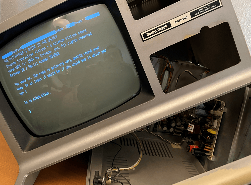
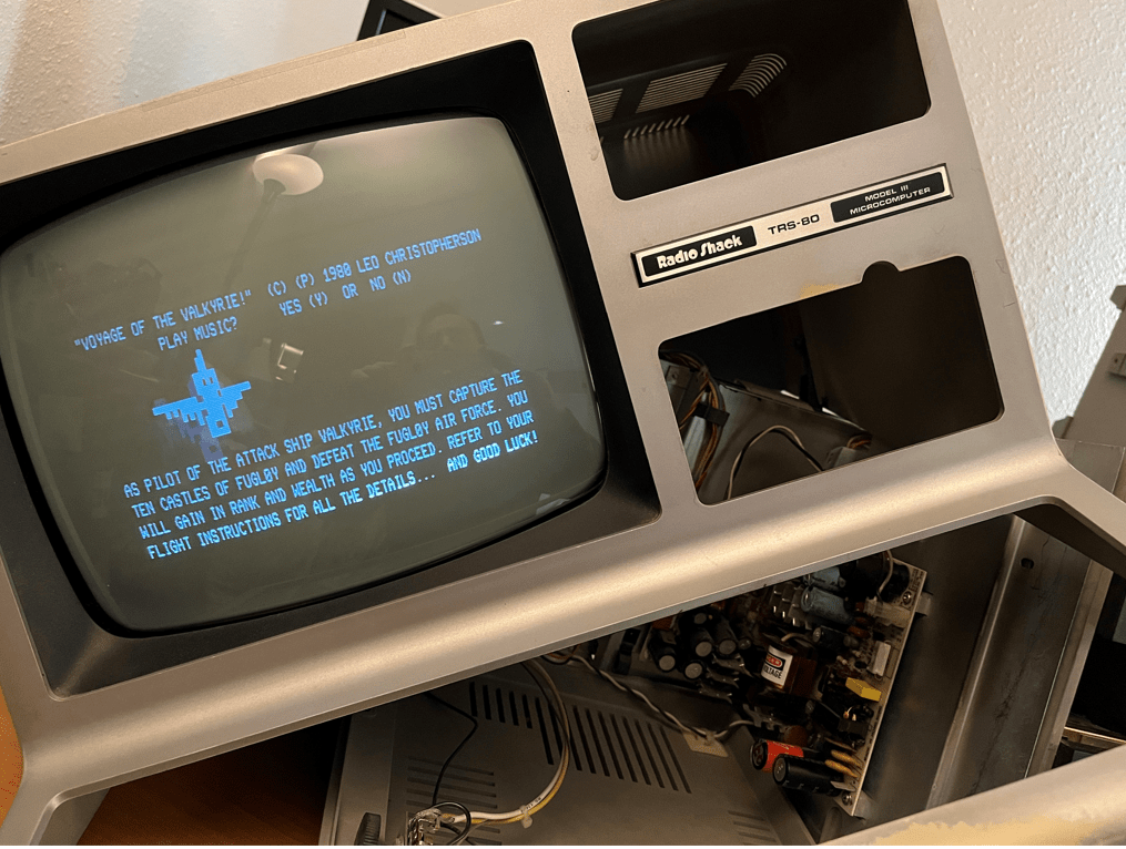
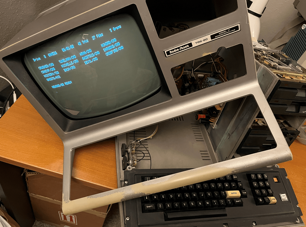
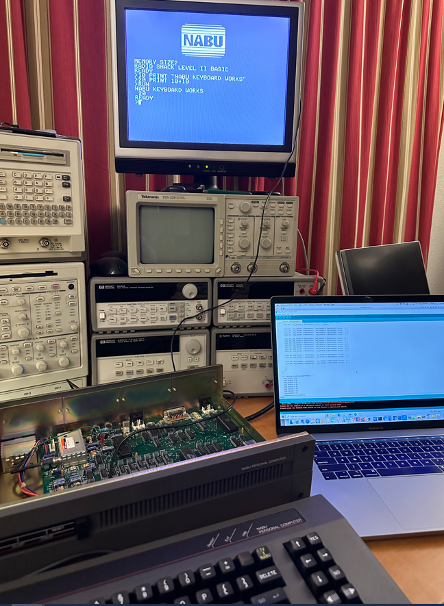
So, that’s about it! The NABU now boots to the splash screen and then runs the TRS-80 Model I Level II BASIC. Below are a few pictures of the machine in action.
The code is here on GitHub:
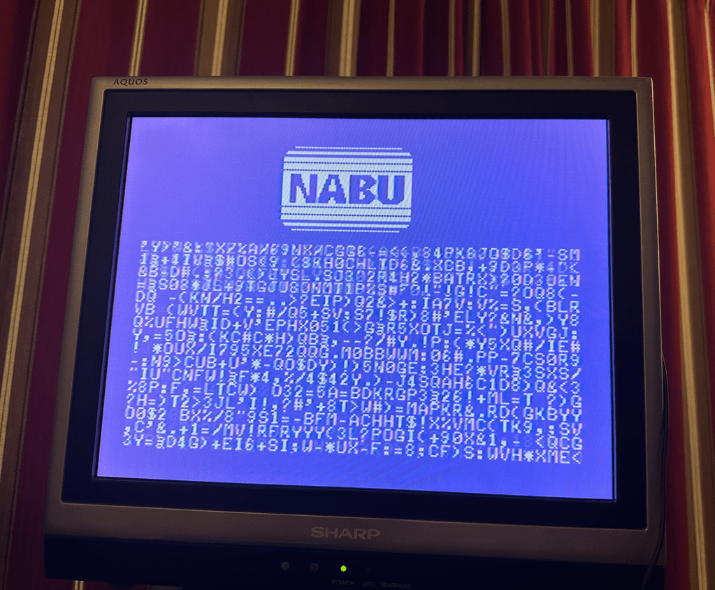
This is a picture of random characters sent to the NABU’s video RAM. It was interesting to find that I need to add a delay of at least 50 uS between each write or else I would get corruption. I guess the chip needed time to transfer the write over to the dedicated video memory…
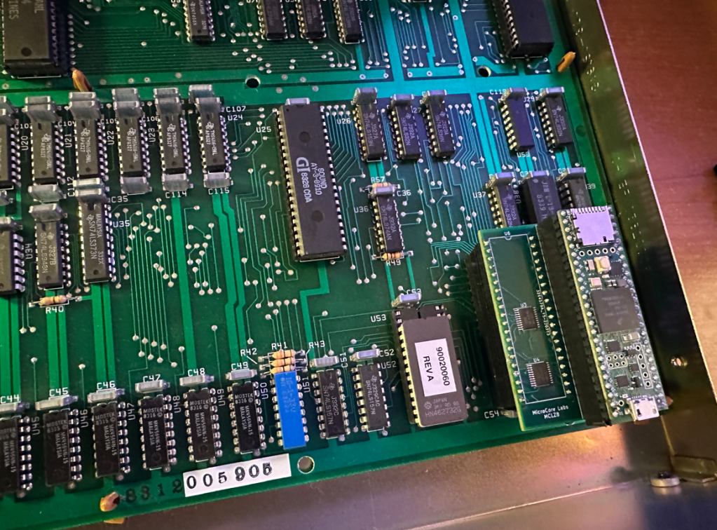
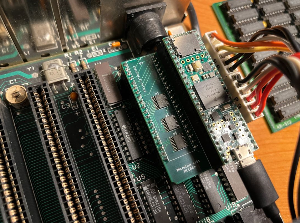
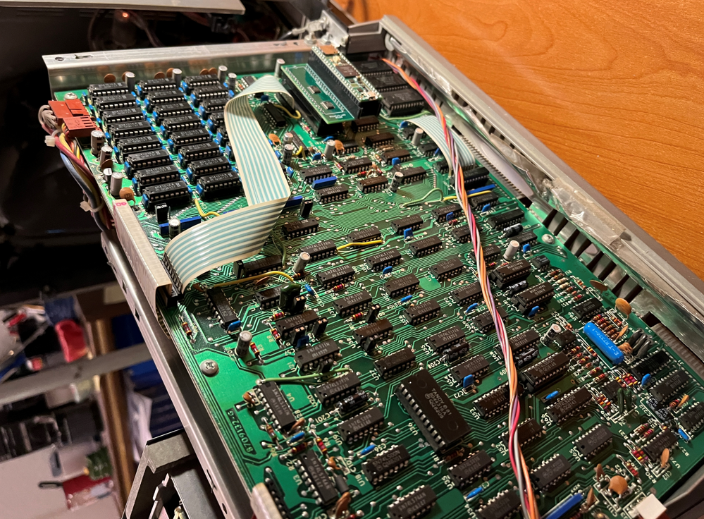
Here’s a picture of the MCLZ8 board replacing the Z80 CPU in the NABU motherboard
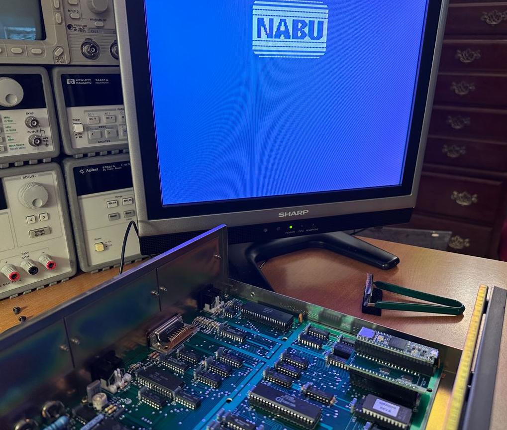
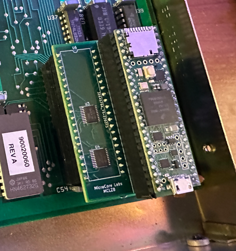
And here is a close-up of the MCLZ8: