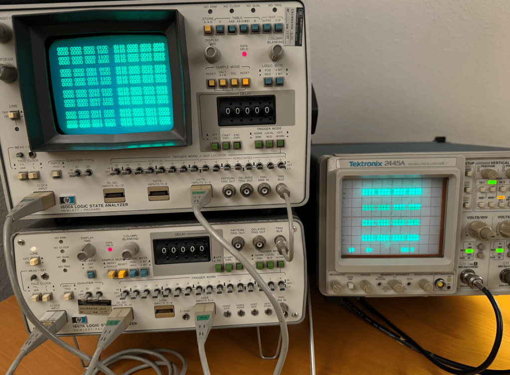
I got the HP 1607A, which was previously non-functional, up and running!
I opened up the machine today and poked around looking for faults in a power rail, but upon first look every rail seemed ok. The voltage rails +5v, +12v, and -12v all looked fine.
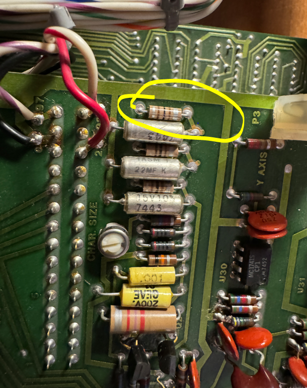
The next step was to understand why the Z-blanking signal which is output at the rear of the machine was missing… I spent the next fifteen minutes or so tracking backwards until I found the source of the problem which was a missing 100 khz clock. The issue was some issue in this circuit:
It turns out that 5Vf was missing. I tracked it back to an earlier schematic page and it appears to be sourced from an inductor.
I grabbed my soldering iron and swapped this guy out…
I picked up a vintage HP 1600A/1607A logic analyzer set over the weekend which was state of the art back in 1975. I thought I would see if I could at least get them running and functional and then maybe develop some interesting stunt!
I was surprised that the 1600A was able to power up and render anything onto the display considering the fifty year old caps could be totally dried out by now and kept the power supply from working… The buttons were a bit sticky but none appeared broken.
The HP 1607A, however, was not able to send a sync signal on the Z channel, so in this case I do think there is an issue with its power supply likely due to dry caps. I will debug this machine some other time…
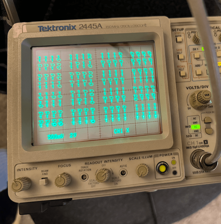
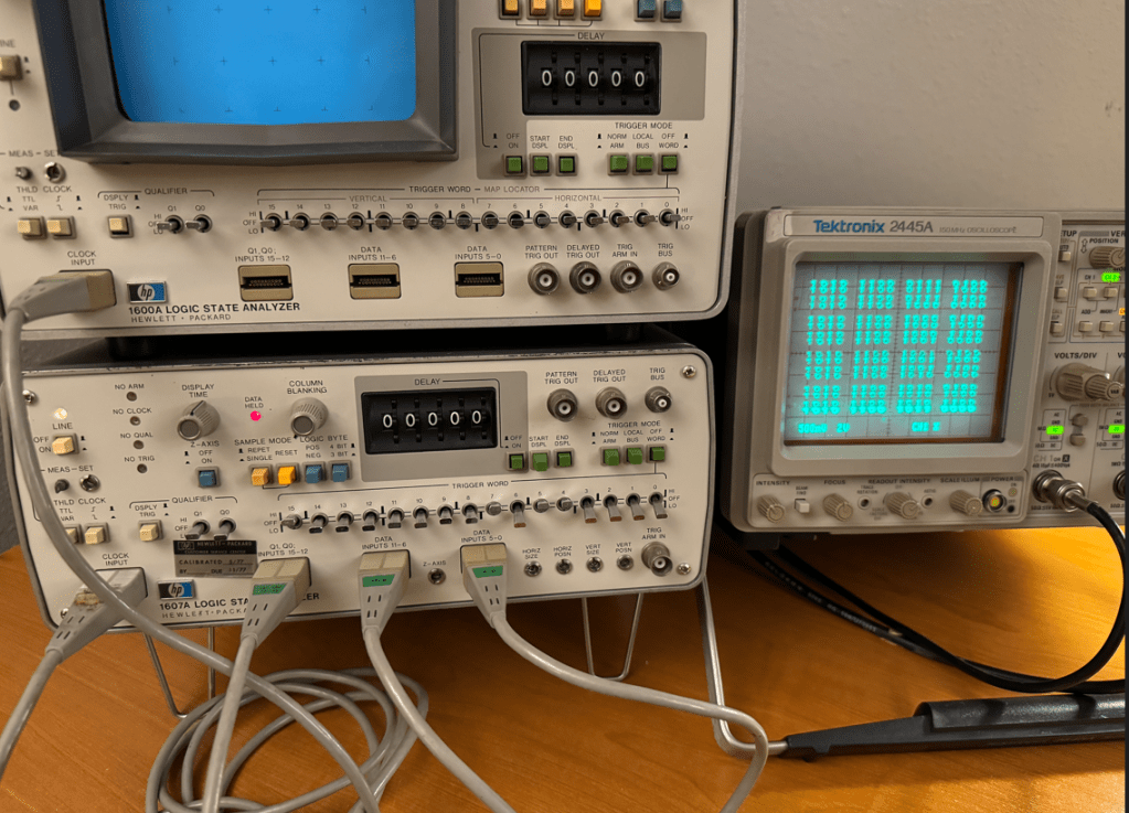
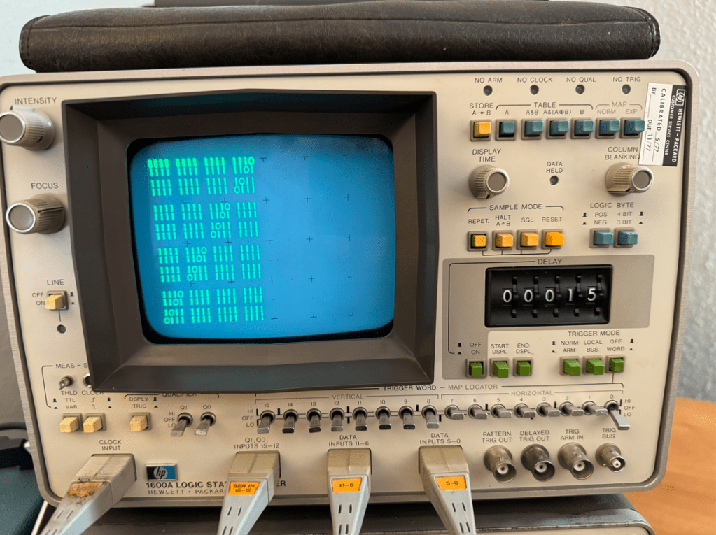
Since the HP1600A is a logic analyzer, the logical next step to test it would be to develop a way to generate stimulus, so I decided to employ a Teensy 4.1 to provide 32 data signals and two clock outputs. I whipped up some code and had a nice pattern on the analyzer in no time. One thing I found interesting was that when this unit is used as stand-alone, the 16 channels are justified to the left…
This was fun for about two minutes, so I began to look for a way to make this analyzer do something more interesting…
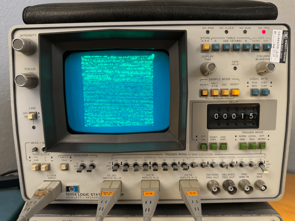
This analyzer also has a “MAP” function which is basically an addressable X-Y mode that allows the user to write to any of the display’s 64×64 pixels. This is enabled with the MAP switch at the top right. but it was not operating consistently due to the stickiness, so I had to take the machine apart to use contact cleaner on all of the switches and dials that I could reach.
Here is the offending switch which I doused with contact cleaner:
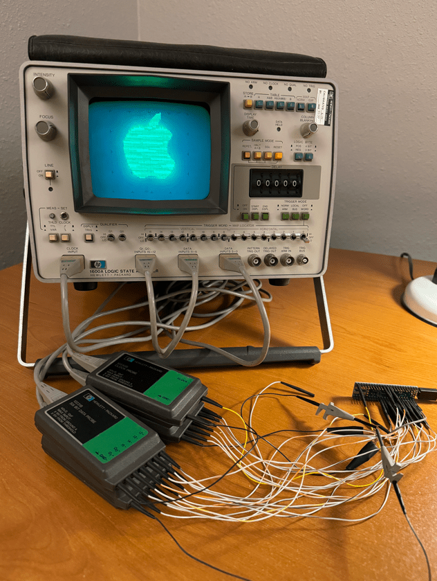
Once the machine was reassembled, MAP mode worked fine, so I made a small program to write pixels in random locations all around the screen which was much more interesting than walking-bit number paterns!
The next step after that was to try sending images to the display. The best way I know to do this is by using images stored in BMP format which, for B&W images has either a 0 ot 1 for each pixel in the image.
I used GIMP to resize and export the images to a BMP file and made a small C program to convert and send the 64×64 image to the format used by the logic analyzer’s MAP mode to display on the screen.
When seen in real life the image has a very pleasant shimmers. Im guessing it may be because I am sending screen refreshes faster than the machine expects or was designed to handle, but is any case it looks nice… 🙂
The next step will be to crack open and debug the HP 1607A, but that’s a project for another day!
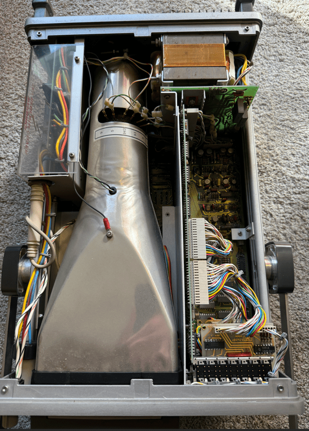
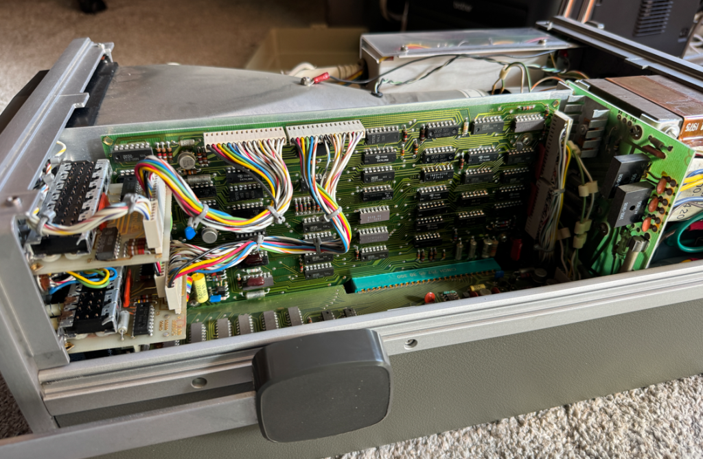
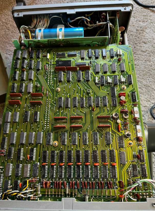
Here are a few more pictures of the insides of the HP 1600A: