IBM PC 8088 replaced with a Motorola 68000

I was wondering what the IBM Personal Computer would have been like if they had chosen the Motorola 68000 instead of the Intel 8088, so I used my MCL86+ to emulate the 68000 and find out!

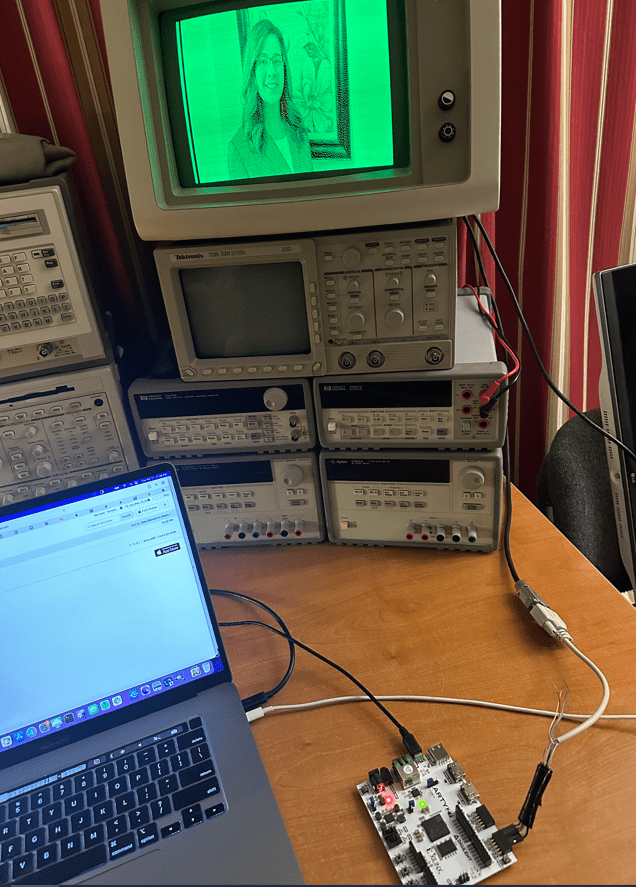
The MCL86+ is a board which uses a Teensy 4.1 to emulate a microprocessor in C code as well as use its GPIOs to emulate the local bus of the Intel 8088. It can be used as a drop-in replacement for the Intel 8088 and can be cycle accurate as well as run in accelerated modes.

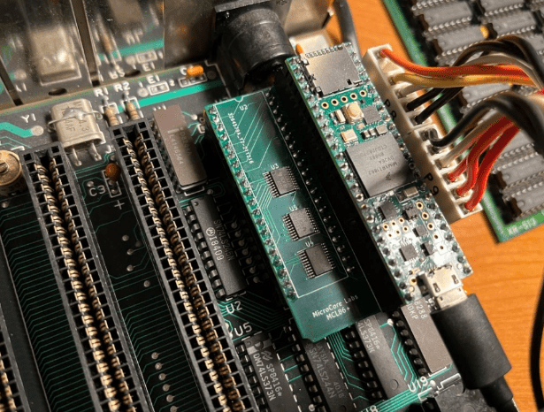
For this project I swapped the 8088 emulation code with my MCL68 code which emulates the Motorola 68000. The 8088 local bus emulation was kept so that all of the 68000’s memory reads and writes could pass through to the IBM motherboard.

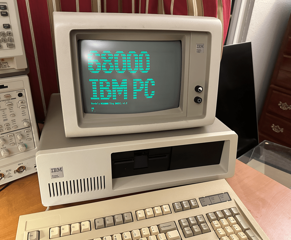
Emulating the 68000 is fine, but not very useful without an operating system or some other application to run on it. I chose to use Gordon Brandley’s 68K BASIC which was published in Dr. Dobbs Journal back in 1985.

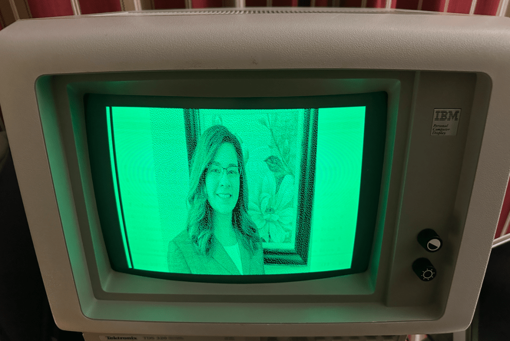
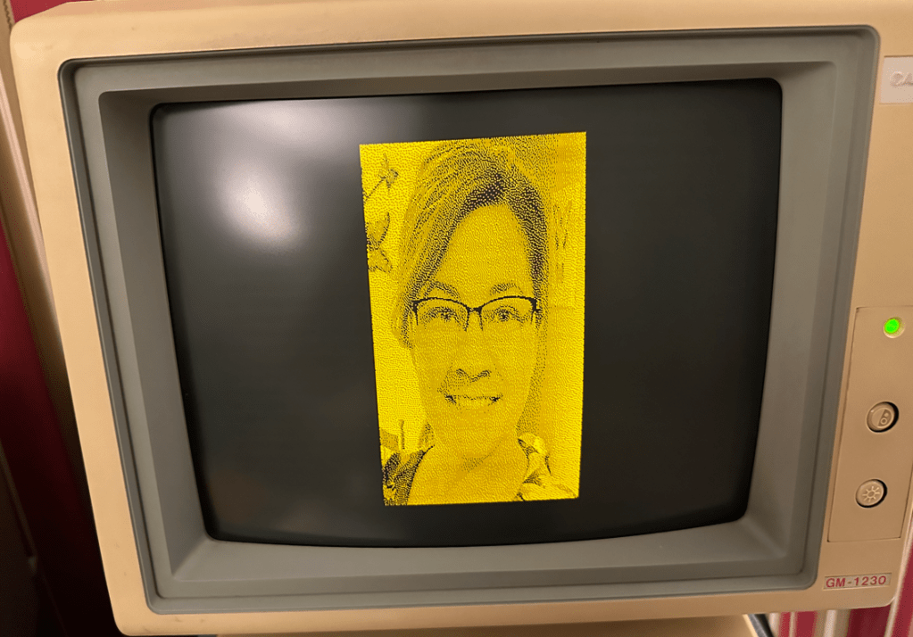
I should note that just the 68000 emulation is running inside of the MCL86+. All of the IBM motherboard peripherals, video, and memory are used for this project. Video is drawn to the IBM MDA card’s video memory over the ISA bus. BASIC is run out of 64 KB of the motherboard DRAM which is refreshed by the 8327 DMA controller by an interval set by the 8253. The keyboard receives the serial data and generates an interrupt through the 8259 and is cleared by accesses to the 8255. Basically all of the major components and glue logic of the IBM motherboard are used!

I ran a few tests and it seems that there is not much of a performance difference between running an 8088 and a 68000 on the IBM motherboard which uses 8-bit chips exclusively. If IBM had chosen the 68000 they may actually have used the 68008 which is a 68000 with an 8-bit local bus interface. Perhaps this chip was not available at the time IBM’s project, code-named ‘Chess’, was in development. It could also have been the case that Microsoft did not have an operating system or BASIC ported to the Motorola 68000 architecture. What this project shows is that the performance difference was not so profound that it would have made a difference in IBM’s selection process.

Here are some videos of the machine in action:

I hope this project helped satisfy those who have wondered what the IBM Personal Computer would have been like if they had selected the Motorola 68000 instead of the Intel 8088!

IBM PC 8088 replaced with a Motorola 68000

MDA Video SOC FPGA Project

This is a small project which uses an SOC FPGA to display images to the IBM 5151 MDA display I just repaired.

Code is on GitHub: https://github.com/MicroCoreLabs/Projects/tree/master/MDA_Video

I am using a Digilent Arty Z7-20 SOC FPGA development board which contains a 600 Mhz ARM processor and has access to 500 MB of DRAM.

The FPGA core contains a 720-bit wide dual-ported RAM and a small state machine to fetch each display row and generate the MDA display timing.

Images are held in an array in the C code running on the ARM core which is then copied down to the dual-ported RAM in the FPGA code. This makes it easier to reload new images rather than storing the images in the FPGA core’s configuration bitstream.

The image array holds the full 720×350 bit image with one bit per pixel . It is generated by using GIMP to convert the original JPEG image to the appropriate size and color, then save as a BMP image. This image file is then converted to an array using a small C program I wrote.

I made this small cable to connect the MDA signals to the FPGA’s PMOD connector inputs.

This setup also worked on my amber MDA display.

MDA Video SOC FPGA Project

IBM 5151 Repair

I came into possession of an IBM 5151 MDA monitor which was in rough and non-functional condition. There was a raster on the screen but no video. My sense was that most of the circuitry was working and that the problem would be with something small-signal or digital as opposed to related to a high-voltage circuit.

After probing the power rails I found that the +5V was missing.

The damaged part candidates could be R214, C202, the transistor TR18, the IC201 or the zener diode D0203. I pulled each one in this order and found that it was the zener diode which was shorting to GND. Of course the last device I test..

To confirm the theory that the missing 5V was the only issue with the display I sourced this voltage with a bench supply. Thankfully the display began to work!

I had two options: One was to simply replace the diode but I would have to wait a few days/weeks until the delivery arrived, and the other was to replace this circuit with an LM7805 which is a 5V linear regulator which I could harvest from my parts bin – today!

So this is what I did. I removed the resistor R214 and connected the linear regulator’s input to the 14V at R214’s pad.

This solution worked great!. Here you can see the display working with the regulator mounted on the bottom-side of the PCB.

After making a few adjustments to the internal POTs it was ready to put back together and give a good scrubbing with a Magic Eraser.

IBM 5151 Repair